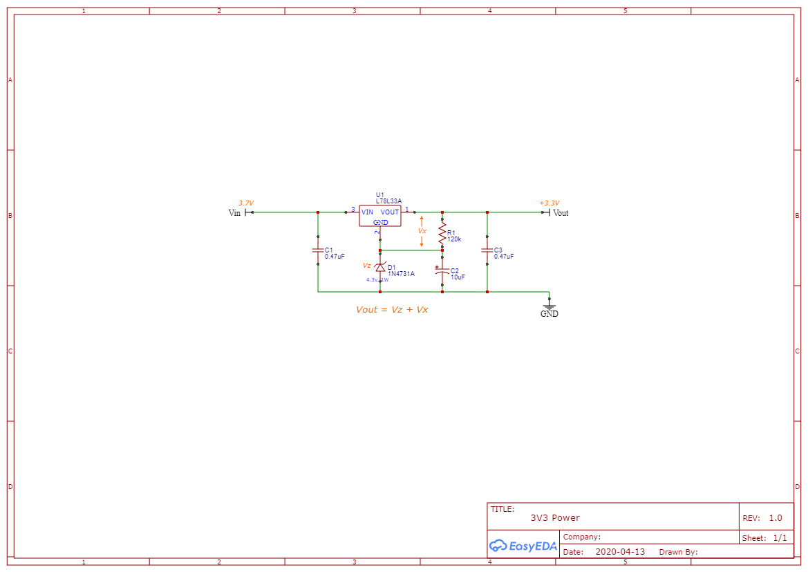
to start with, I am very new to the hardware side so don't beat me up too much.
For a project I am doing I need to build a couple power rails, one 3.3v and another 24v. The power supply will be from a 3.7v 1A LiPo battery.
I started on the 3.3v first, I already had a 3.3v fixed voltage regulator (L78L33A), so I figured I could probably just use this, in the datasheet showed a schematic but didn't have the zener diode and resister values and I don't yet know how to calculate these so I figured I would just play around with different values to see what I could come up with.
I set my benchtop supply to 3.7v, 1A for testing and after playing around a bit I got a nice 3.3v output, still don't understand it but eventually I will learn.
Then, I hooked up the battery and did not get the same 3.3v output, instead it was much lower and when I probed right at \$Vin\$ with the battery in, I would get ~2.5v, however, when I probe the battery without it hooked up to anything I got ~3.9v.
I'm wondering why the results are different and if this is normal to have the different results? If this is, then should I have instead tested using on the battery since that is what it will ultimately be running off of?
Here is the schematic with the values I ended up with (I will start a new question about how to figure out Vz/Vx/R1).
Thanks!
Update 01
Based on the answers and comments, clearly this is def wrong for what I'm trying to do, I was reading the schematic for a boost circuit, will take the suggestions and try this again.

