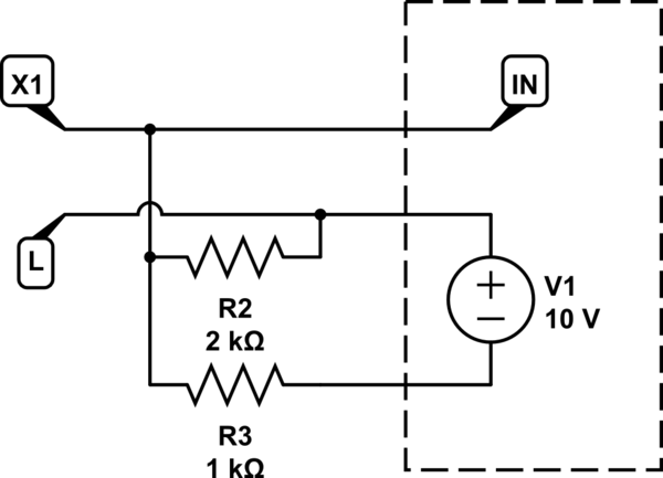
Goal is to be able to use standard wall 2 gang light switch to:
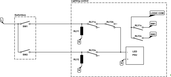
a) provide line connection with either of two / both hot wires coming from the same 230VAC phase to the ceiling for AC-DC 48V PSU powering DC-DC buck driver, LED array.
b) be able to differentiate with MCU which one / both of hot wires is powering the lamp for setting one of 3 brightness levels according to the active combination of switches' states:
right switch - left switch - brightness
ON - OFF - minimal
OFF - ON - medium
ON - ON - maximum
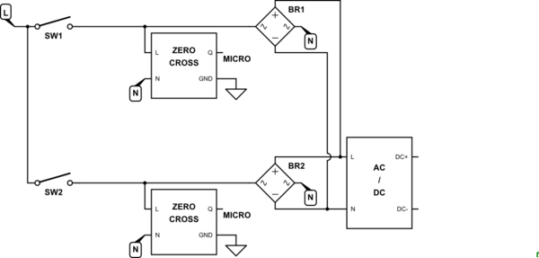
So how do I design a circuit to know which of two switches is powering my lamp or whether both of them are ON?
MCU and other logic could be powered with a separate low power AC-DC module. Delay up to a second for detecting current state is acceptable.
Only ideas that I have involve shunt resistors, differential amplifiers, and etc. to measure and/or compare voltage drop that should be present only across resistors on active wire(s). This seems overall complicated and hard to account for 0-1A input current range.
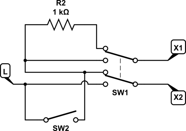
UPD1: My case is not a planned installation, but rather conversion of 2x 150W incandescent lamps (thus existing 2 gang switch and 2 wires in the wall) to a single LED array. It is possible to change that wall switch with an alternative that fits existing 68mm cylindrical electrical box, but chances that I will find anything as fancy as DPDT switch are pretty low. I will take a look though.
My existing PSU is Meanwell LRS-200-48.
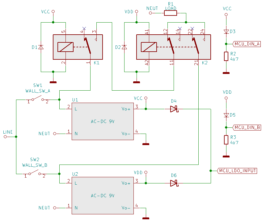
UPD2: I tried solution with relays (see finalized schematic below) and it works as intended. I do not have 230VAC relays at hand so I tried it with 3x SRD-05VDC-SL-C general purpose ones and NA05-T2S05-V AC-DC units (pdf) as a proof of concept. As expected there was ~1 second load brownout (while turning off SW2), which is acceptable IMO. I could buy something like 230VAC rated RTE24730 to lower the switching time, but I decided against it for 2 reasons. Firstly, it would consume ~1.6W per coil, instead I can operate 12V relay at 9V with 0.23W per coil. Secondly, it means waiting delivery from Mouser and spending 6-9 USD per relay, while I can buy 12VDC RTE24012 locally for 2-3 USD. And I still have to provide my MCU with power, so either this or a dedicated DC-DC converted from 48V that I'll probably would have to make myself. So buying couple of AP09N05-Zero is well worth $8. I tested these PSUs, they have great specs even without input&output filters and manufacturer is pretty ensuring comparing to something like HLK-PM09 / HLK-5M09 which floods the market.
D3, D5 are to ensure that MCU absolute maximum requirement for digital input of VCC+0.2V is not exceeded. This was for 5v AC-DC modules, so read a proper voltage divider here..
R2, R3 placed near input pins is to make sure there would be no 50hz noise (somehow I was reading up to 2VAC measured with 10MOhm DMM unless I loaded it with a simple 1.5mA LED).

