1
\$\begingroup\$

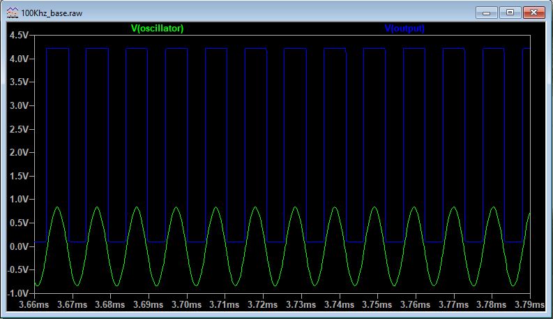
I am trying to build an LC meter for measuring capacitance variations based on an LC tank Oscillator and an LM311 comparator. I took the circuit from this source (https://www.schiessle.de/emt1/MessKleinKap/MessKleinKap1.htm), and I would like to stick with that circuit as much as possible. I first simulate the circuit in LTspice to get an idea on how the circuit works. I want the LC circuit to oscillate around 100 kHz, and in the simulation, the results are good.

enter image description here

However, when I built the circuit, the results differ from the expected values. As a first step I made the circuit on a protoboard, and I checked it with a nScope USB oscilloscope.

I included a bypass capacitor from the power supply to ground, I connect the balance and strobe pins of the LM311, and I also used a different L1 inductance value of 2.7mh (therefore the oscillating frequency should be around 96Khz) that is not ideal (it has a 23ohms component). The components that I am using have, except the capacitor C3, 10% tolerance value.

The problem is that the circuit becomes damped and noisy after a few seconds, and I can not find why. I try modifying the C3 value. The bigger the value of the C capacitor, the longer it lasts in a stable way. I tried placing another 1mF capacitor in parallel to C3 and it works.

video here: https://youtu.be/F3j8kqEoxcw

Could these issues be caused because of building the circuit in a regular protoboard and not on a PCB? What else could be the problem? Any comments will help!

Thanks in advance!

\$\endgroup\$
3
  • \$\begingroup\$ Why is the output pin of the LM311 connected to the LM311's Vcc pin? Don't use this oscillator design - it is unorthodox and brings nothing to the party in terms of theory or transferability to a different device. Someone has found it works and hey presto, "it must be a good design". It isn't so don't use it. There are much more orthodox and "proven" oscillator circuits that use a comparator and a tuned circuit to generate a sine wave. \$\endgroup\$
    – Andy aka
    Commented May 6, 2020 at 11:30
  • \$\begingroup\$ According to your schematic C3 would be a polarized i.e. electrolyte capacitor and in you picture it looks like it - is this really the case? Are you aware of the nature of such caps? \$\endgroup\$ Commented May 7, 2020 at 9:06
  • \$\begingroup\$ Yes, I am using a polarised capacitor for C3 but on the simulations worked fine. Would this have such an impact? And what is weird is the behaviour after a few seconds. At the beginning works fine (as shown in the video) \$\endgroup\$
    – Mahuertar
    Commented May 7, 2020 at 20:58

1 Answer 1

0
\$\begingroup\$

using a very-high-gain high-current-surges LM311 on a protoboard...... is asking for constant mis-behavior.

============================

By the way, simulators will do NOTHING with a polarized cap, at least in my experience. That is not modeled in the CAP model within SPICE.

\$\endgroup\$
2
  • \$\begingroup\$ I've removed unnecessary cables and the frequency value improved, now it is close to the desired value. However, the signal keeps becoming noisy and damped after a few seconds. I will try to solder the components on a PCB in the next days. \$\endgroup\$
    – Mahuertar
    Commented May 6, 2020 at 21:23
  • \$\begingroup\$ surprisingly the problem was solved by connecting directly the +Vcc pin of the LM311 to 5volts. In the source (schiessle.de/emt1/MessKleinKap/MessKleinKap1.htm) and in several approaches I found in internet, they connect it through a 1K resistor. \$\endgroup\$
    – Mahuertar
    Commented May 11, 2020 at 21:05

Your Answer

By clicking “Post Your Answer”, you agree to our terms of service and acknowledge you have read our privacy policy.

Not the answer you're looking for? Browse other questions tagged or ask your own question.