1
\$\begingroup\$

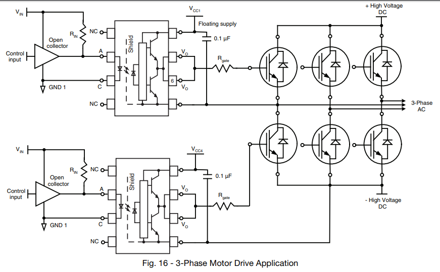
I want to use in my project an isolated optocoupler like this one to switch an IGBT. In the following schematic, taken from this Vishay application note there's a "floating supply" in Vcc1 as you can see:

enter image description here

I'd like to understand what it means. Should I connect the positive of my power supply in Vcc1 and let the common of the supply disconnected? Or the common should be connected to the emitter of the IGBT?

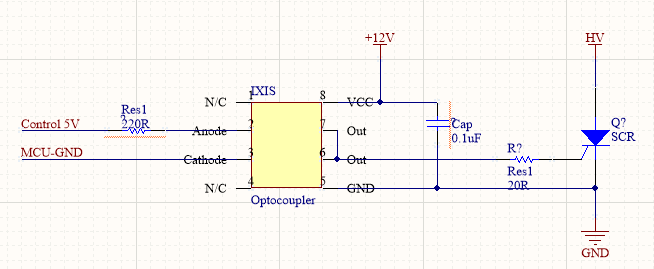
Another question: This same circuit would work well driving a SCR too? Like this:

enter image description here

Again, 12V and HV power supplies should have the same common?

\$\endgroup\$

2 Answers 2

1
\$\begingroup\$

The VEE of the upper optocoupler can be connected to the + High Voltage DC (by the upper IGBT's) or to the -High Voltage DC (by the lower IGBT's).
Therefore the power supply of the optocoupler cannot have a negative terminal which is connected to -High Voltage DC as it can short to +High Voltage DC when an upper IGBT turns on.
Most times the reason for using optocouplers is to provide galvanic isolation. Therefore the negative terminal of the power supply can neither be connected to GND1 (quite confusing the appended the same 1 here...) because it eliminates the isolation.

Best is to use separate isolated 12V supplies for each optocoupler.

Should I connect the positive of my power supply in Vcc1 and let the common of the supply disconnected?

No, a supply needs a return. So, with only Vcc1 connected, the optocoupler will not be powered/working. So, the negative terminal of the isolated 12V should be connected to VEE.

Or the common should be connected to the emitter of the IGBT?

Yes, provided you use isolated 12V supplies.

Another question: This same circuit would work well driving a SCR too?

Because the VEE of the optocoupler is only connected to the (HV) GND you can connect the negative terminal of the power supply to this (HV) GND and do not need a floating/isolated power supply.

\$\endgroup\$
3
  • \$\begingroup\$ Thanks. Just to be sure: if I need to control a SCR and an IGBT that will conduct to the same GND (I mean, the cathode of the SCR and the emitter of the IGBT will have the same connection) I can use the same 12V supply to control them? \$\endgroup\$
    – Rohde
    Commented May 6, 2020 at 19:20
  • 1
    \$\begingroup\$ @Rohde Yes, assuming you use the circuit as the last picture in your question and a second equivalent circuit where the SCR is replaced by an IGBT. \$\endgroup\$
    – Huisman
    Commented May 6, 2020 at 19:46
  • \$\begingroup\$ If I connect several 220V:12V transformers to the same outlet (e.g. using a power strip) they'll be isolated from each other? They won't share any reference? Thanks again. \$\endgroup\$
    – Rohde
    Commented May 7, 2020 at 3:36
2
\$\begingroup\$

When driving your IGBT bridge, the floating supply on the 'hot' side of your optoisolator must be totally unconnected to the low voltage side. The 'floating' means with respect to the input side.

You will need four isolated supplies, one for the HV -ve, and one for each phase.

Depending on the amount of power you need on the IGBT side, this could be done with a transformer with several isolated secondaries, each driving their own rectifier/capacitor, or you can buy isolated supply modules which use a transformer internally. For a quick test, you can even use batteries.

For the SCR, the 12 V supply GND must be connected to the SCR GND, and ket isolated from the MCU GND.

\$\endgroup\$

Your Answer

By clicking “Post Your Answer”, you agree to our terms of service and acknowledge you have read our privacy policy.

Not the answer you're looking for? Browse other questions tagged or ask your own question.