0
\$\begingroup\$

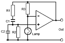
If a circuit like the Wien bridge oscillator below uses an incandescent bulb for automatic gain control, how does this actually vary the gain?

I know that the resistance of the bulb increases as the filament heats up, but I've been told that it can be used as a variable gain element for gain stabilisation. What I don't understand is how it varies.

As far as I can tell, the bulb in this circuit is being used in place of another resistor that forms a voltage divider with R3 which outputs to the op-amp's inverting terminal. If the bulb was replaced with a resistor, R4, I could understand how selecting values for the resistors would allow the user to control the gain, but I don't understand how the lamp does it.

Maybe I'm misunderstanding, but from what I could tell, the lamp was able to control gain automatically, instead of needing to be a chosen value of a resistor. Is it because incandescent bulbs heat up so much that the resistance is constantly increasing? And if this is the reason, how is this property related to the gain of the circuit?

I'm also wondering what is the actual advantage of using these lamps instead of other gain stabilisation methods like JFET or diodes. With most incandescent bulbs not being used any more due to their inefficiency, is there any particular advantage that would mean someone might prefer to use it in their circuit?

enter image description here

\$\endgroup\$
3
  • 2
    \$\begingroup\$ This was discussed a few months ago, see my answer here: electronics.stackexchange.com/questions/485870/… \$\endgroup\$
    – Mattman944
    Commented May 8, 2020 at 14:24
  • \$\begingroup\$ @Mattman944 thanks I've had a read through your answer, but I'm still not completely sure. Does the feedback ratio need to be 2:1 in every Wien bridge, or just that person's specific one? And will the bulb always provide this ratio, as long as R3 is double the bulb's R at the target voltage? \$\endgroup\$
    – MendelumS
    Commented May 8, 2020 at 14:32
  • \$\begingroup\$ @Sam : not a bad question. See if you can calculate the attenuation of the R-C voltage divider R1C1 and R2C2 at the resonant frequency. \$\endgroup\$
    – user16324
    Commented May 8, 2020 at 14:38

3 Answers 3

2
\$\begingroup\$

As the amplitude increases, so does the power dissipated in the filament This raises the filament temperature, hence its resistance, which is arranged so as to reduce the gain, thus stabilising the amplitude automatically.

Why choose a lamp instead of another non-linear resistor (voltage variable resistor) like a JFET or something involving diodes?

What's great about the lamp is that its resistance changes slowly, from the thermal inertia of the filament. Thus the resistance isn't varying to any great extent throughout the sinewave cycle, changing the gain during each cycle, which would add harmonic distortion to the waveform.

So lamp-stabilised Wien bridge oscillators tend to be used where low harmonic distortion is required. 0.01% or 0.003% (-80dB to -90dB) are quite easily achieved; lower THD is possible with care.

(At low frequencies, as the period approaches the filament's thermal time constant, you can see gain decreasing at the peaks of the waveform, in the form of 3rd harmonic distortion).

Thermistors have similar characteristics, and are sometimes used - but the gain has some dependency on ambient temperature too.

\$\endgroup\$
2
  • \$\begingroup\$ I was about to answer the same as the first paragraph but then realized negative feedback is not synonmous with stability. \$\endgroup\$
    – DKNguyen
    Commented May 8, 2020 at 15:47
  • \$\begingroup\$ Such a "resistive integrator" is a good example of the so-called "memristor"... \$\endgroup\$ Commented May 8, 2020 at 20:34
1
\$\begingroup\$

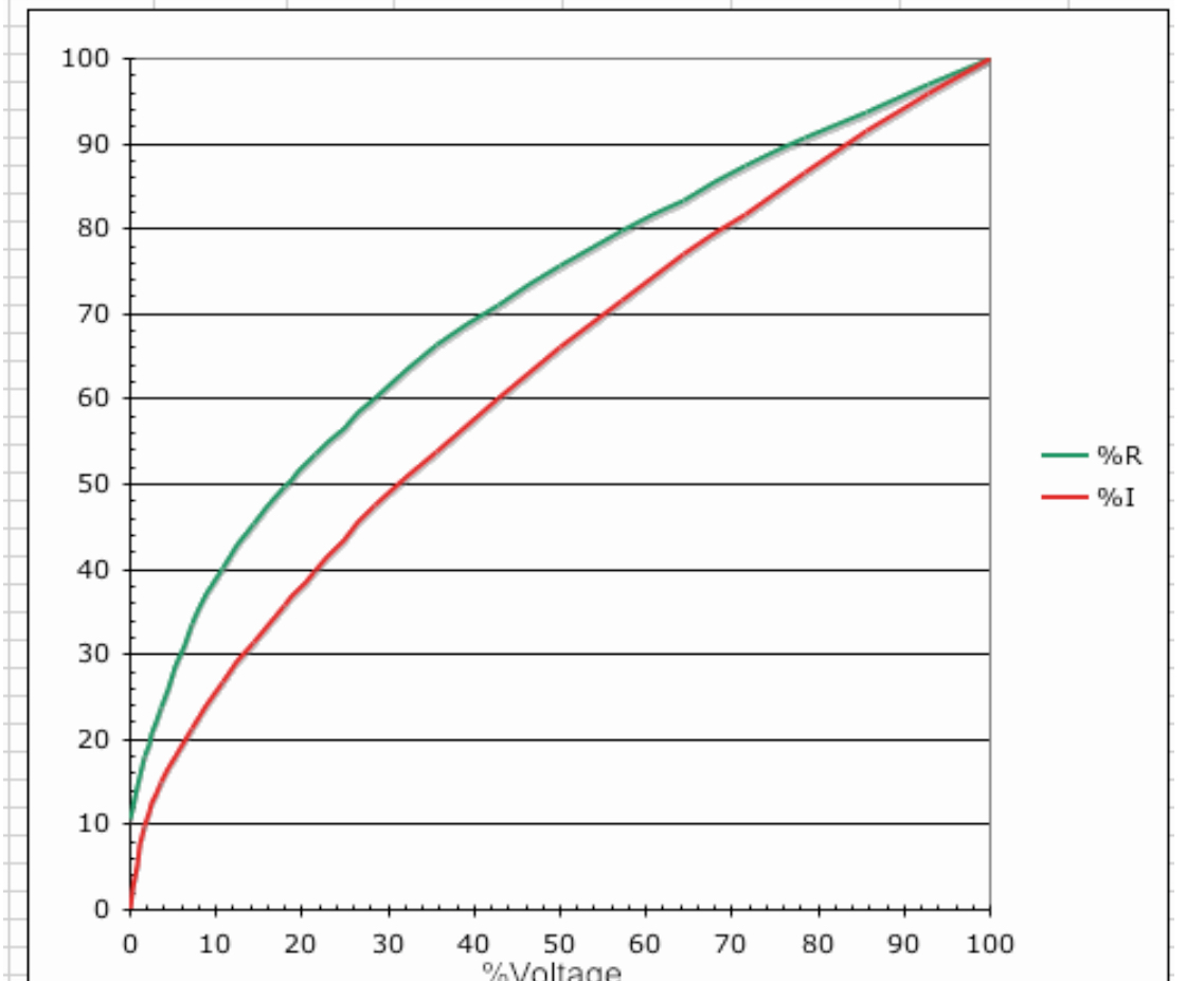
If the output amplitude increases, the lamp voltage increases, and the resistance increases (slowly, as it heats) and thus more negative feedback is applied, stabilizing the output amplitude.

Because the bulb has a natural time constant it provides a low pass filtering effect. It is also very linear at high frequencies so it does not unnecessarily contribute to distortion.

The oscillation decreases to nil if the gain is a bit too low, and it increases until clipping and distortion limit it if the gain is slightly too high, so some form of stabilization is necessary.

This website has good information on the lamp response.

enter image description here

There are other methods such as CdS photoresistors (discouraged or prohibited in some places because of the cadmium) that are also very linear and less linear methods such as JFETs.

\$\endgroup\$
1
\$\begingroup\$

You're almost there already! Choose R3 to pass enough power to heat the filament, and your "R4" (Lamp) becomes self-selecting. In the circuit shown, an increasing "R4" reduces the overall gain by increasing the negative feedback, so you use just enough positive feedback to:

  • Make it start with a cold filament
  • Let it settle as the filament warms up

The filament doesn't have to glow; it only needs to change its resistance.

\$\endgroup\$
1
  • \$\begingroup\$ Since it takes time for the filament to heat or to cool then the amplitude of the sinewave "bounces" up and down for some time after changing frequency or amplitude. \$\endgroup\$
    – Audioguru
    Commented May 8, 2020 at 16:13

Your Answer

By clicking “Post Your Answer”, you agree to our terms of service and acknowledge you have read our privacy policy.

Not the answer you're looking for? Browse other questions tagged or ask your own question.