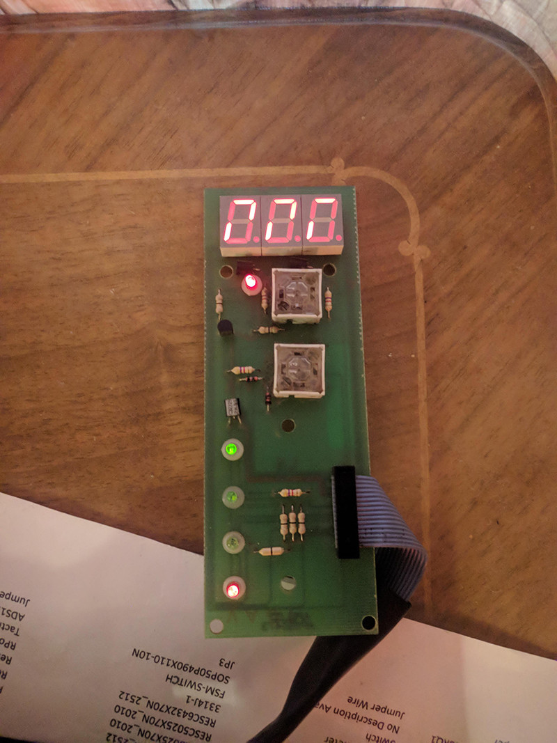
I am trying to get this 20-year-old board working again for a few days now, constantly feeling I am close to the solution, but I can't get it to work.
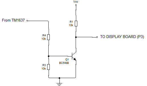
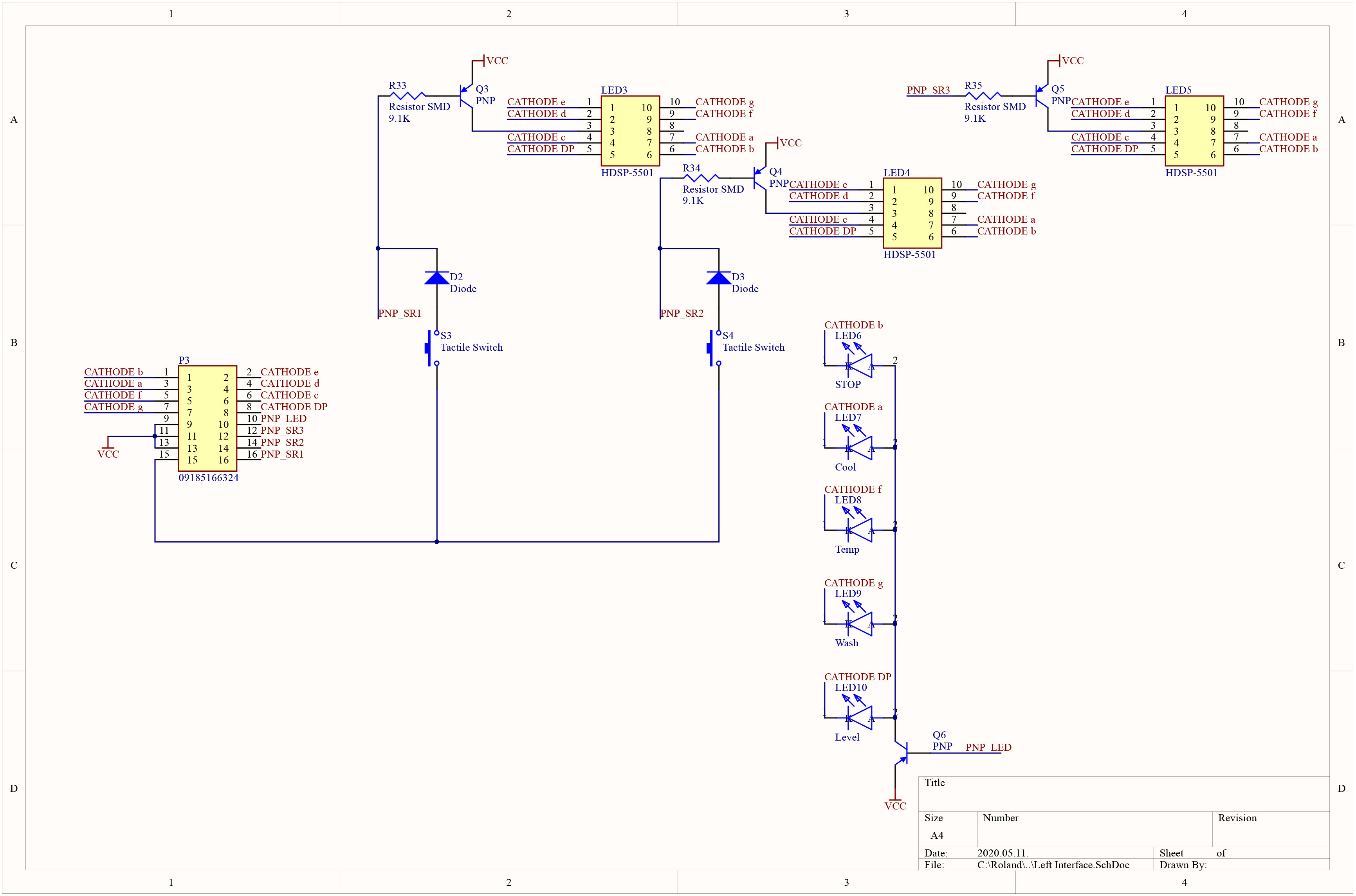
The segments Led[3..5] are wired to connector P3 trough the PNP (BC327) the LED's are also wired as a 4th digit
I'd like to get it wired up to a TM1637 as I have that at me, and only have 2 free pins left on my design. (Datasheet_TM1637)
My problem is that the PNP's are inverting the Common Anode input so none of the screens ligh up.
What I tried:
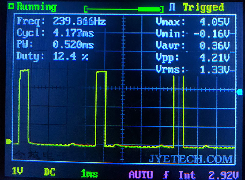
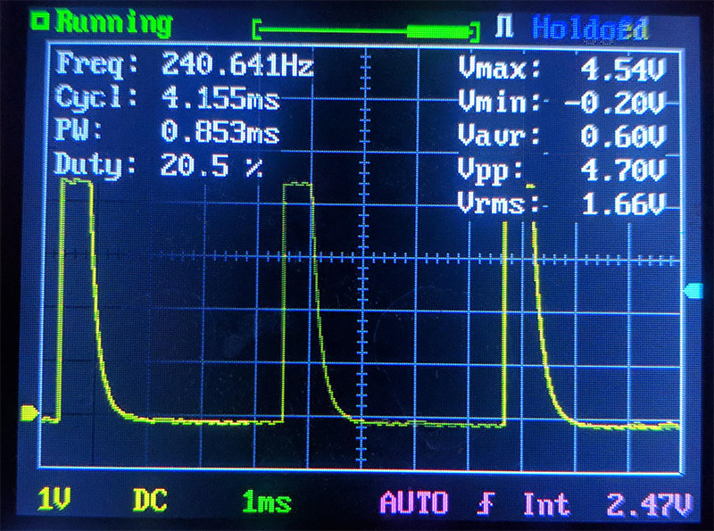
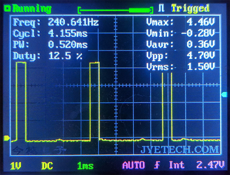
- I pulled TM1637 anode output to GND (10K), and now all of them light up, but some segments are brighter than others, none are totally off, and the output shows up weirdly. Also, the driving signal is pulled up. (Pictures below)
I found some logic IC's on an old board and Recycled them.
- I wired it to an HCU04 but the screens go blank(it's not open-collector)
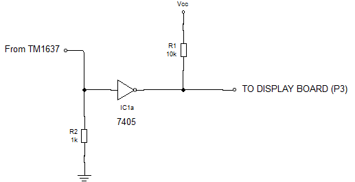
- Also found an SN7405. It's open-collector, but it won't get any output if driven by the TM1637.
If I wire it to the HCU04, than that inverted output to the SN7405, I get back to where I started with the pulldowns. (also can drive the screen)
To be honest I'm not even sure now if the inverting is the problem anymore.
What could I do to get this working?
P.S.:
- I can not change the circuit that is below as it is already on the board. I can connect to it by P3 IDC connector.
- I drafted the schematic, so VCC might be something else. I labeled it based on the PNP's.
- Some current limiting resistors are placed on the cathode lines (other side of the IDC) I'm not sure if they are needed when using TM1637.
- S[3..4], and D[2..3] are buttons for a weird input but that's a whole other story.
- The Italians who designed the baord back in 2001 used a 74HC374 to drive this screen
I made a sketch of the circuit:
Sorry for the lame scope
Unconnected Output:
 Pulled Low:
 Screen Connected:
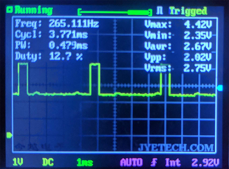 Negate:
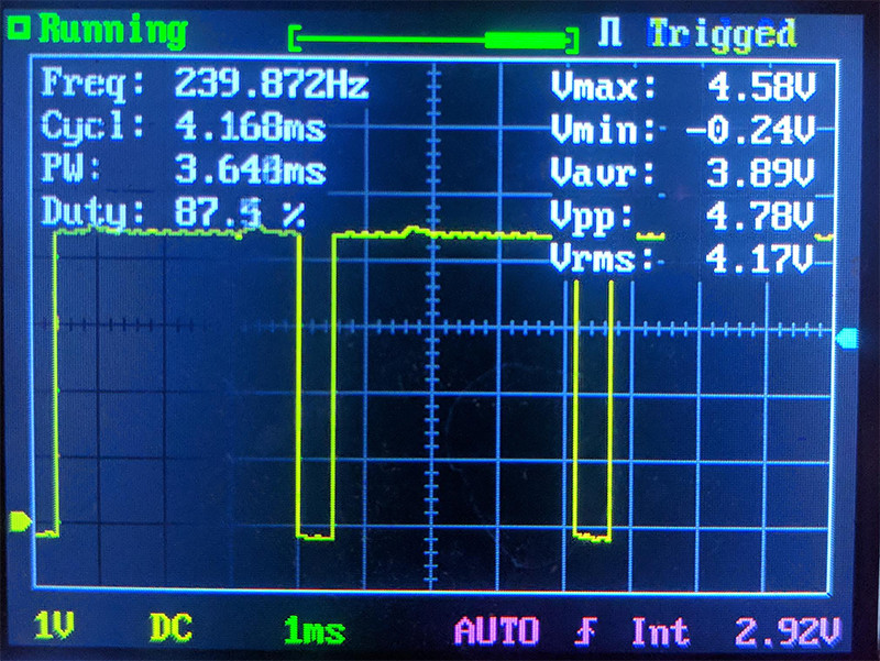 Negated Open Collector:
