0
\$\begingroup\$

I'm trying to implement a rectifier and AC voltage sensor. The rectifier part works just fine. I'm able to power my device without any issues.

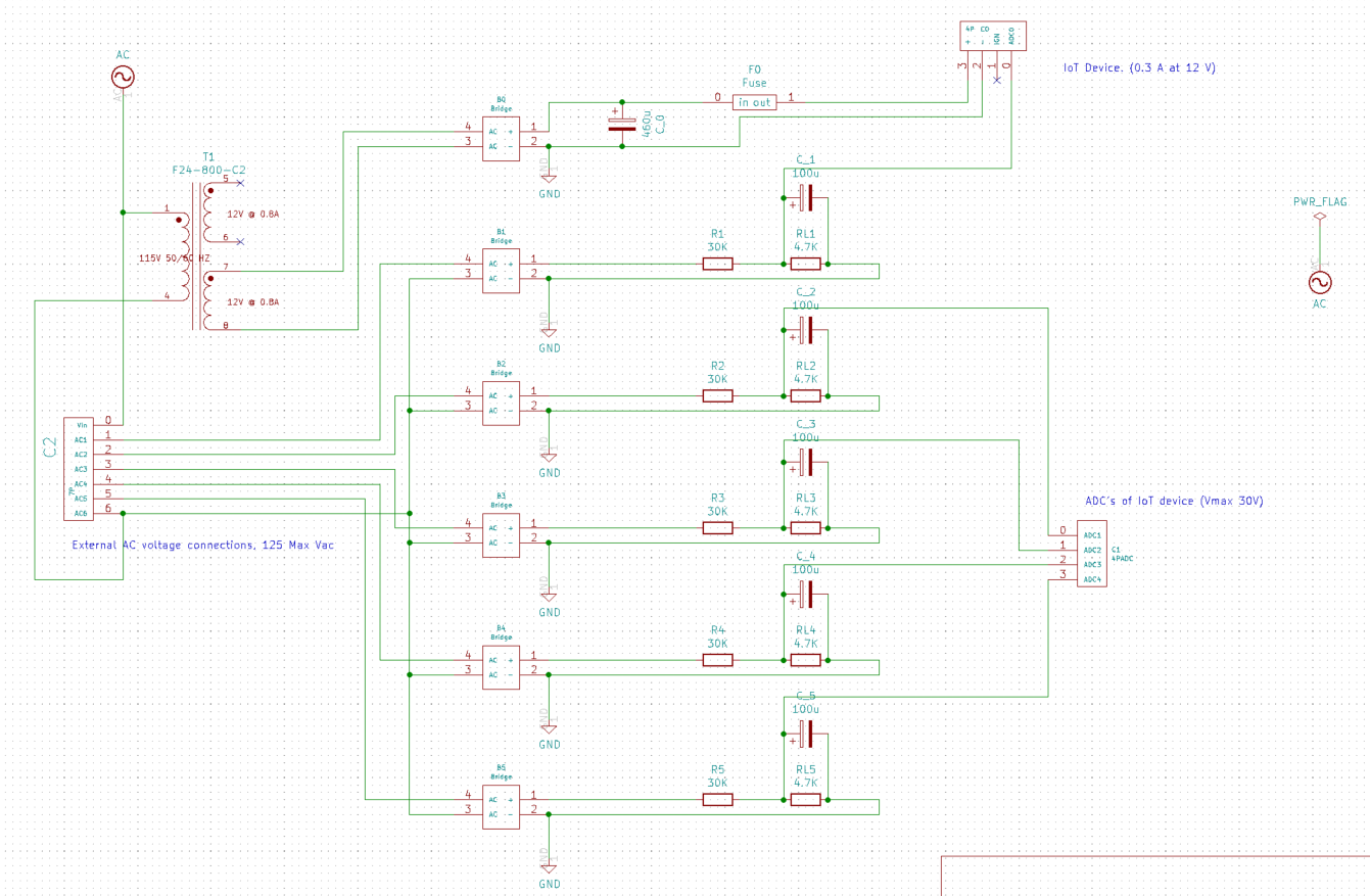
Please look at C2 in the screenshot (Circuit schematic). This connector is connected to AC voltages. Vin is rectifier and the DC part is to power the device. AC-1 to AC-5 are AC voltages that are sensed at ADC-0 to ADC-4 respectively. AC-6 is the neutral line of all the AC voltages connected to the board.

When AC (1-5) are connected to AC voltage, the device works just fine. No issues at all. But when AC-1 and AC-2 are connected to 120 VaAC while AC (3,4 and 5) are not connected to anything, ADC-0 and ADC-1 read the right value but ADC (2,3 & 4) read 7.5V while they should read 0 V.

I connected all the -ve terminals of the bridge rectifiers to have a common ground but when there is no AC voltage, the respective +ve terminals of the bridge rectifiers reads 58V (+ve is floating while -ve is grounded). Is there any way to fix this? cause my ADC is reading the incorrect value of 7.5V when it should read 0 V.

Thank you enter image description here

\$\endgroup\$
3
  • \$\begingroup\$ I can't comment on the existing answer as I'm new here, but what is controlling the heating elements, what device is turning them on or off? Solid state relays or SCRs will have some voltage leakage through snubber / driver circuit. If relay, contactor or switch then there should be no voltage, possibly just capacitive coupling or induced voltage is being picked up? Adding some kind of pull down resistor to disipate induced voltage might be needed? \$\endgroup\$
    – zxhoon
    Commented Aug 27, 2020 at 1:49
  • \$\begingroup\$ When you say "not connected to anything" is that LITERAL (ie. nothing is connected to those pins on connector C2)? BTW, please don't name connectors C?, P? or J? would be better. \$\endgroup\$ Commented Aug 27, 2020 at 2:17
  • \$\begingroup\$ It's been a while. Did you fix the obvious faults in your circuit, or abandon the project? \$\endgroup\$ Commented Aug 27, 2020 at 6:23

3 Answers 3

1
\$\begingroup\$

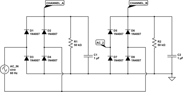
There is no ghost voltage, it can be calculated exactly. The channels without AC input receive half wave rectification through the other rectifiers with input. I just have drawn 2 rectifiers in detail as example to show it. Just look at the simulator output:

schematic

simulate this circuit – Schematic created using CircuitLab

Assume AC_IN is just positive at the bottom connector. Current will flow via D6, R2 and D3. And this without AC_2 connected to anything. In the other half wave CHANNEL_B receives no current from AC_IN.

\$\endgroup\$
0
\$\begingroup\$

You can simply add high value resistor from floating point to default reference point

\$\endgroup\$
8
  • \$\begingroup\$ The floating-point is the +ve terminal of the bridge rectifier while the default reference point is ground of the -ve terminal of B0 bridge rectifier... Also all the -ve terminals of bridge rectifiers are connected to the -ve of the B0 bridge rectifier. ... So essentially I'm just putting a load of that resistance across the bridge. This does not accomplish what the circuit is suppose to do ... \$\endgroup\$
    – varun
    Commented May 13, 2020 at 16:20
  • \$\begingroup\$ Okay let me see. Why AC have common pin(AC6) may be your wrong reading doesn’t cross by floating. \$\endgroup\$
    – M lab
    Commented May 14, 2020 at 0:06
  • \$\begingroup\$ I'm sorry ... I don't understand... Are you saying have one neutral for 5 hot wires is the problem? \$\endgroup\$
    – varun
    Commented May 14, 2020 at 2:48
  • \$\begingroup\$ Okay let me see. Why AC have common pin(AC6) may be your wrong reading doesn’t cause by floating. I don't know where AC come from and why it have common neutral? \$\endgroup\$
    – M lab
    Commented May 14, 2020 at 12:31
  • \$\begingroup\$ All these AC voltages belong to a heater module. I'm reading these voltages at different points inside the heater module. If there is 120V AC, that means a certain submodule of this heater is ON. Else it's OFF. that's the purpose of this board. Hence they all have common neutral. \$\endgroup\$
    – varun
    Commented May 14, 2020 at 14:59
0
\$\begingroup\$

It sounds like to me you have AC feedback leaking through. Perhaps. We call it "Ghost voltage" measure your earth to neutral on your input, if you have 5 volts (AC) or higher across input neutral and earth, you have a problem with your AC supply. Your bridge is taking in two references and it will cancel each other out and yes you will have no output. Your circuit looks good to me bud. Make sure your DC ground and AC earth is not clashing. Persist, persist and never give up. Dream about the fault of you must.

\$\endgroup\$
3
  • \$\begingroup\$ "Dream about the fault of you must." Welcome to EE.SE but we don't speak that lingo here. \$\endgroup\$
    – Transistor
    Commented Aug 27, 2020 at 13:58
  • \$\begingroup\$ Yes! I did fix the problem. Te reference voltage was the issue. So I added Earth ground and referenced all the voltages to it. Then Instead of using bridge rectifier, I used Differential opamps. It worked, I made the board as well. Tested it for 2 weeks. Ran it continuously for 2 days and nothing heated up or anything. Its all good now. Thank you \$\endgroup\$
    – varun
    Commented Aug 27, 2020 at 19:32
  • \$\begingroup\$ @Transistor what's wrong with the Reverse Polish notation? \$\endgroup\$
    – fraxinus
    Commented Oct 11, 2021 at 18:06

Your Answer

By clicking “Post Your Answer”, you agree to our terms of service and acknowledge you have read our privacy policy.

Not the answer you're looking for? Browse other questions tagged or ask your own question.