-3
\$\begingroup\$

Figure

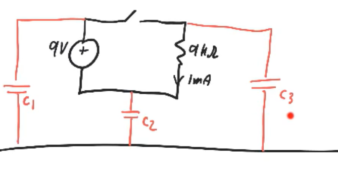
In the figure, the circuit is physically isolated from Earth (The black line at the bottom). The red capacitors are parasitic capacitors.

Under switching conditions the node voltages relative to the zero reference swing in such a way that the internal charge in the circuit stays the same. This is understandable because the circuit is isolated from ground and cannot get more charge or lose any charge. So the charges internally rearrange themselves in a way that leads to the node voltages being what they are.

Question: How is this possible. Is this internal rearrangement of the charges a current? If so then is this current different from the “normal” current of the circuit (The 1mA)?

What I think is correct:

I think that Electric fields that change and exist between charged bodies will cause something like current flow, called displacement current, such that a change in the electric field on one body affects the electric field on a nearby body. But how does this affect the 1mA current that appears in the circuit?

In summary:

Does the internal rearrangement of the charges in a circuit create a current? If it does then is this current different from the “normal” current of the circuit (The 1mA)?

\$\endgroup\$
2

1 Answer 1

0
\$\begingroup\$

Electricity does not need a ground to work. Current just flows around in loops. Charge is conserved. Voltages are only something that are evident across things, a voltage is only with respect to something else.

BUT: We live on the Earth, which is really big thing of mostly iron. This big conductor which dominates our environment does affect the electricity around us. However, it’s effect is mostly obvious at high frequencies, and we usually ignore it. For DC, It is so big that if a little charge flows into it, it’s voltage with respect to the center of the universe hardly changes. But, charge does flow into it and out of it, and we should not let it’s size convince us that charge conservation does not apply.

Instead of drawing the ground as a big black line at the bottom of your schematic, collapse the line to a single node in the middle of the drawing. When the switch is open, C3 and the resistor in series are across C2. This combo is in series C1, all across the voltage. When the switch is closed, C1 and C3 are in parallel, in series with C2, and connected across the voltage.

Thus, charge does redistribute among the capacitors when the switch is actuated, as the voltage across them changes. Your confusion arises because you are letting a node you called “ground” be something special. (And perhaps it is special, just not for the analysis of this problem.)

\$\endgroup\$
1
  • 1
    \$\begingroup\$ Hi, Since this question has been closed as a duplicate, you might want to delete this answer and post it on the original question instead, so that your answer doesn't get deleted with this duplicate question. It's your choice :-) Thanks. \$\endgroup\$
    – SamGibson
    Commented May 16, 2020 at 19:14

Not the answer you're looking for? Browse other questions tagged or ask your own question.