3
\$\begingroup\$

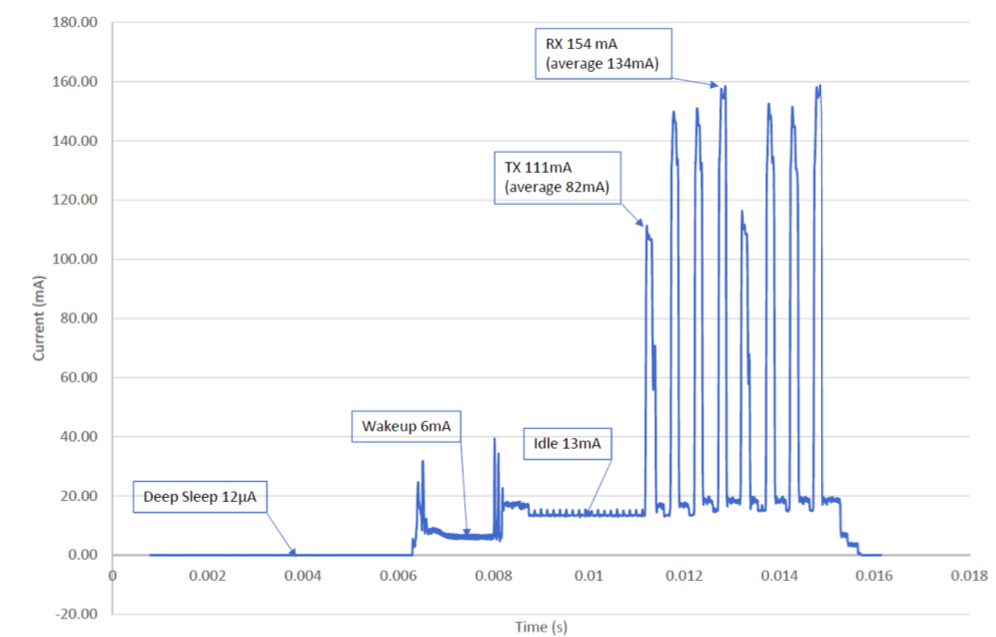
I am making a RF circuit which could operate using a 3V coin cell battery like CR2032 or CR2450. In sleep mode it consumes around 10-20uA but during Tx/Rx which lasts for 10ms it consumes ~300mA-ms. My circuit works in 2.8-3.6V range. To supply this surge current I have tried using a 1000uF capacitor and it has performed well except when handling the startup inrush current.

Now to increase battery usage I am planning to use a boost converter with low Iq like : http://www.ti.com/lit/gpn/tps61322. I couldn't use 2 coin cells (6V) and an LDO as I want to keep the form factor smaller and battery replacement easier.

My doubt is if I am using a boost converter, would I still require a capacitor parallel to the battery so that battery is not subjected to high current surges or a boost converter can inherently take care of such surges without drawing too much current (~10-15mA) from the battery.

More details: Attached is the graph showing current vs time during the Tx/Rx operation. In total it lasts for approx 10ms and consumes about 300mA-ms. Once this Tx/Rx is done the circuit goes to sleep and consumes 10-20uA Current Profile for Tx/Rx

The overall current profile of the RF circuit looks like:

Complete current profile including sleep and Tx/Rx

\$\endgroup\$
2
  • \$\begingroup\$ Comments are not for extended discussion; this conversation has been moved to chat. \$\endgroup\$
    – Voltage Spike
    Commented Jun 9, 2020 at 5:44
  • \$\begingroup\$ You'll need a capacitor parallel to the output of the boost converter. In fact, every boost converter needs this. \$\endgroup\$ Commented Sep 15, 2021 at 9:11

2 Answers 2

2
\$\begingroup\$

Any kind of converter must obey the energy conservation law, so

$$ V_{out} \cdot I_{out} = V_{in} \cdot I_{in} - P_{losses} $$

Or also

$$ V_{out} \cdot I_{out} = \eta \cdot V_{in} \cdot I_{in} $$

Where \$\eta\$ is the efficiency of the converter.

Therefore inverting that equation gives: $$ I_{in} = \frac {V_{out}} {\eta \cdot V_{in}} \cdot I_{out} $$

That law must be obeyed at any instant of time, not on average.

So a prerequisite for your design to work is that it works in the worst possible scenario, which is when the output current is maximum, the output voltage is set to its maximum and the input voltage is minimum.

For a ballpark calculation let's assume:

  • \$ I_{out(max)} = 140 \text{mA} \$
  • \$ V_{out(max)} = 3.6 \text{V} \$
  • \$ V_{out(min)} = 2.5 \text{V} \$ (worst case is when the battery is almost discharged; we assume 2.5V is its cut-off voltage).

The datasheet you linked to reports an efficiency of about 90% at 150mA and 2.5V input voltage, so we will assume \$ \eta = 0.9 \$.

Plugging these values into that formula gives you:

$$ I_{in} = \frac {3.6\text{V}} {0.9 \cdot 2.5\text{V}} \cdot 140 \text{mA} \approx 224 \text{mA} $$

For good measure let's round that to 250mA for a bit of safety margin. This means that you should expect peaks of at least 250mA at the converter input in the worst case. Is your battery able to provide that? If not, you must add a capacitor and see if that helps (you must also consider the cap ESR and the input resistance of the converter).

\$\endgroup\$
0
\$\begingroup\$

First some rules of physics.

  • All loads have an equivalent impedance for each state.
  • All batteries like electrolytic capacitors have an Effective Series Resistance (ESR) and Capacitance , C [F] where the change in capacitance can be measured in Ah or mAh
  • the product of ESR *C is a function of cell chemistry and bulk size and may be used to compare.
  • any DC supply voltage in a somewhat linear mode will drop voltage according to the resistive divider or Load Regulation formula.
    • Vdrop = I * ESR = Vo-Vi = ESR/(ESR+Load).
    • where desired is ESR < 1% R load for performance reasons.
    • ESR rises rapidly below 10% state of charge (SoC) and rises slowly with aging effects ( heat, under/over charge , cycles, ambient temp)
  • for any given chemistry (primary or secondary) the ESR is inverse to Ah capacity ( for a single cell)
  • ESR multiplies for cells in series *(S) and divides for cells in parallel (P) and all must be matched.
  • Hybrids may be S x P arranged for suitable voltage and current and thus source impedance.
  • All electrolytic caps and batteries have memory such that after a short, they return to a resting voltage. - This is a secondary ESR2*C2 equivalent circuit. There may be more.
  • Compute the energy loss in a large cap and see if that is worth buffering the ESR.
    • E=1/2 CV^2=VI*t

Now go choose a battery that has an acceptable Vdrop and Capacity at desired load current..

Converters do not add energy, mainly change impedance ratio. BE conservative.

\$\endgroup\$
2
  • \$\begingroup\$ Considering the limitation to be able to use widely available coin cells only (as I want user ease in change of battery as its a commercial project), I have zeroed down to CR2032 and CR2450. This I am taking as my absolute minimum requirement. Assuming this I am trying to create a circuit which could power this RF circuit with these 3V batteries only. As per my calculations and not considering all the factors you listed but just the ESR of the circuit + battery,Vo,Vi, one 3V battery and assuming capacitor needs to provide enough charge to power 1 Tx/Rx cycle I am getting ~1000uF as capacitor \$\endgroup\$
    – mosdkr
    Commented May 28, 2020 at 18:14
  • \$\begingroup\$ Secondly given my RF chip has a minimum voltage requirement of 2.8V, I was exploring if a boost converter would be a good idea. I understand no additional electronic component can ever increase the battery mAh capacity. But specific to this case if I can use battery below 2.8V my "effective" battery usage could increase. Would you please suggest if this would be a good strategy: to use a 1000uF capacitor (for handling pulse currents) and a boost converter (to increase effective battery usage of the circuit) \$\endgroup\$
    – mosdkr
    Commented May 28, 2020 at 18:16

Your Answer

By clicking “Post Your Answer”, you agree to our terms of service and acknowledge you have read our privacy policy.

Not the answer you're looking for? Browse other questions tagged or ask your own question.