PTC's are intended to thermally react faster than the load and save on costly repairs due to a fault condition.
If you have an application where you are operating near the absolute maximum current of the conmponent, then PTC may not be what you need.
If you consider an H bridge application with high peak switching currents during transition and shoot through spikes that increase with motor load lagging the turn off time then a deadly time duration of this event can quickly fuse open your FETs. In this case you want an active current limiter with a large capacitor to provide the short transient high current pulses. *( Even better you want dead-time control on commutation)
*
The PTC is intended to protect from thermal overload due to current so
the PTC response time ought to be faster than the unit being protected
but still the source must not exceed the components abs. max current
spec in the short term.
The quickest parts are the smallest SMD PTC's. < 0.1 sec < 1 watt dissipation. such as 1206 or 805.

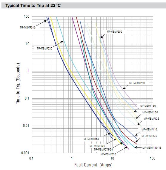
Above is response for a high current PTC sensor

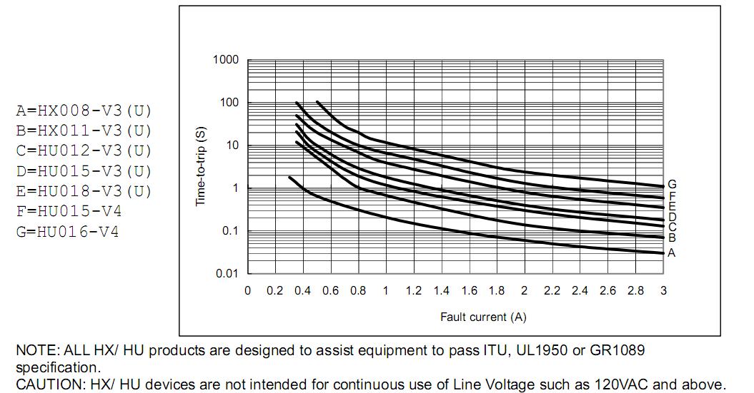
Above is for low current radial PTC starting with 80mA hold current at bottom for HX008

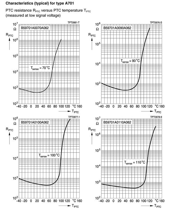
Above is for SMD 805 PTC showing resistance curve vs temp here being used as a thermal protection sensor rather than current limiter due to high cold resistance. (pref. thin track)
It should be clear that ALL PTC's are design to have dynamic impedance
rapidly change at a similar temperature for same material. Some are
standard 85'C others offer different threshold temps which affect your
operating environmental range. See above variation)


