0
\$\begingroup\$

I am trying to design an audio amplifier circuit using BJT These are the requirements of the circuit Input signal: 50-100 mV (It's the output of my iphone's mic) 2W-4ohm speaker There is no requirement for DC voltage source. I can choose so as to feed enough for my circuit. Here's my approach enter image description here I choose to use 12V DC source and design my circuit into two blocks. The first block is an EC amplifier stage which is to amplify my voltage according to the requirement. The second block is for power amplifier, in which I choose emitter-follower as driver stages before a push-pull circuit. I want to use class A stages in that position for impedance matching and to increase the total gain of the power amplifier
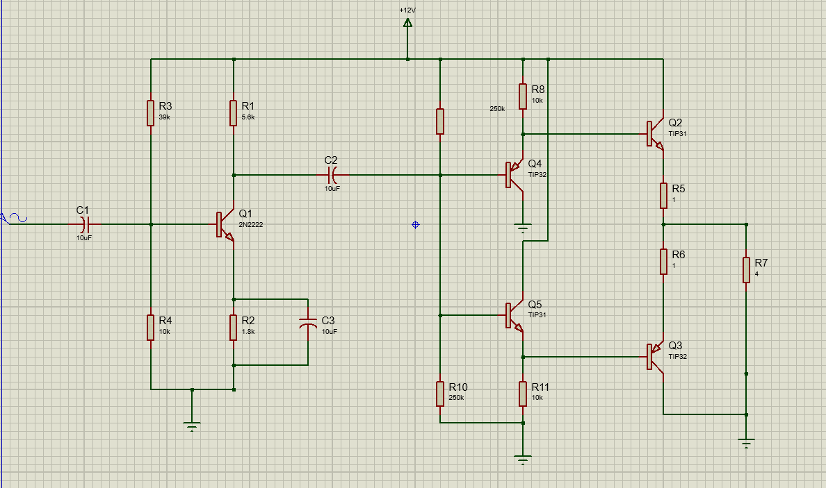
But the problem is my power amplifier stage doesn't seem to work and the output of the first stage is just 2V peak (It is expected to be 4V peak)

Is my design reasonable? If yes, what's wrong with it?

\$\endgroup\$
4
  • \$\begingroup\$ Vc=5.6VDC at the first stage, so there's about 6V headroom before clipping. Hence the max gain can be 6V/100mV = 60. But in your circuit it's >200. \$\endgroup\$ Commented Jun 2, 2020 at 10:42
  • \$\begingroup\$ The first stage take the input impedance of the class A PA as its load so I considered it as well to calculate the total gain \$\endgroup\$ Commented Jun 2, 2020 at 11:31
  • \$\begingroup\$ Are you sure the next stage is a Class A PA? The top and bottom parts are just emitter followers. And their input impedances are high enough to neglect. In Class A amplifiers the output is taken from the collector, not the emitter. Why don't you check the waveforms with oscilloscope? \$\endgroup\$ Commented Jun 2, 2020 at 14:26
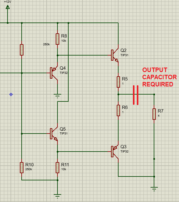
  • \$\begingroup\$ @RohatKılıç You're right! Exactly it's emitter-follower not Class A PA. Sorry for that. I forget a capacitor at the output and now it's been fixed. The problem left is that the result is not as expected. I think I need more calculations. Do you have any recommendations? \$\endgroup\$ Commented Jun 2, 2020 at 15:14

1 Answer 1

3
\$\begingroup\$

I'm not ruling out other things but, the lack of an output capacitor is a pretty significant omission: -

enter image description here

\$\endgroup\$
6
  • \$\begingroup\$ The 1 ohm emitter degeneration resistors also seem a bit big for a 4 ohm load, but I'm no analog design expert so I could be wrong. \$\endgroup\$
    – Joren Vaes
    Commented Jun 2, 2020 at 12:01
  • \$\begingroup\$ @JorenVaes yes, probably around 0.5 ohm or a tad less would be effective and more power efficient. \$\endgroup\$
    – Andy aka
    Commented Jun 2, 2020 at 12:03
  • \$\begingroup\$ @HenryNguyen to understand why of this answer, check electronics.stackexchange.com/questions/469627/… @ Andyaka I hope I am linking correct things to each other, if not please let me know and delete this comment. \$\endgroup\$
    – muyustan
    Commented Jun 2, 2020 at 12:03
  • \$\begingroup\$ @muyustan yes the speaker would suffer with a DC current but the centre-rail bias point of the amplifier would be screwed without the output capacitor. \$\endgroup\$
    – Andy aka
    Commented Jun 2, 2020 at 12:05
  • 1
    \$\begingroup\$ @Andyaka You're right. It's really a big mistake. Thank you very much! \$\endgroup\$ Commented Jun 2, 2020 at 13:00

Your Answer

By clicking “Post Your Answer”, you agree to our terms of service and acknowledge you have read our privacy policy.

Not the answer you're looking for? Browse other questions tagged or ask your own question.