0
\$\begingroup\$

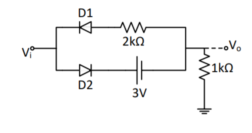
Vo for the clipper circuit where Vi = 10sin (6280t) and diodes are 0.6 volts. enter image description here
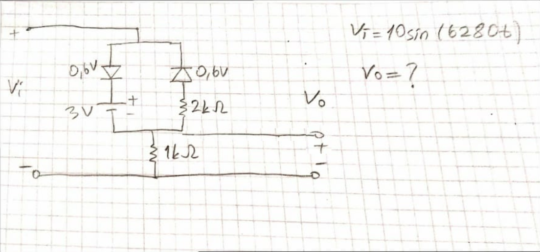
I think the simple form of the circuit is like this. enter image description here
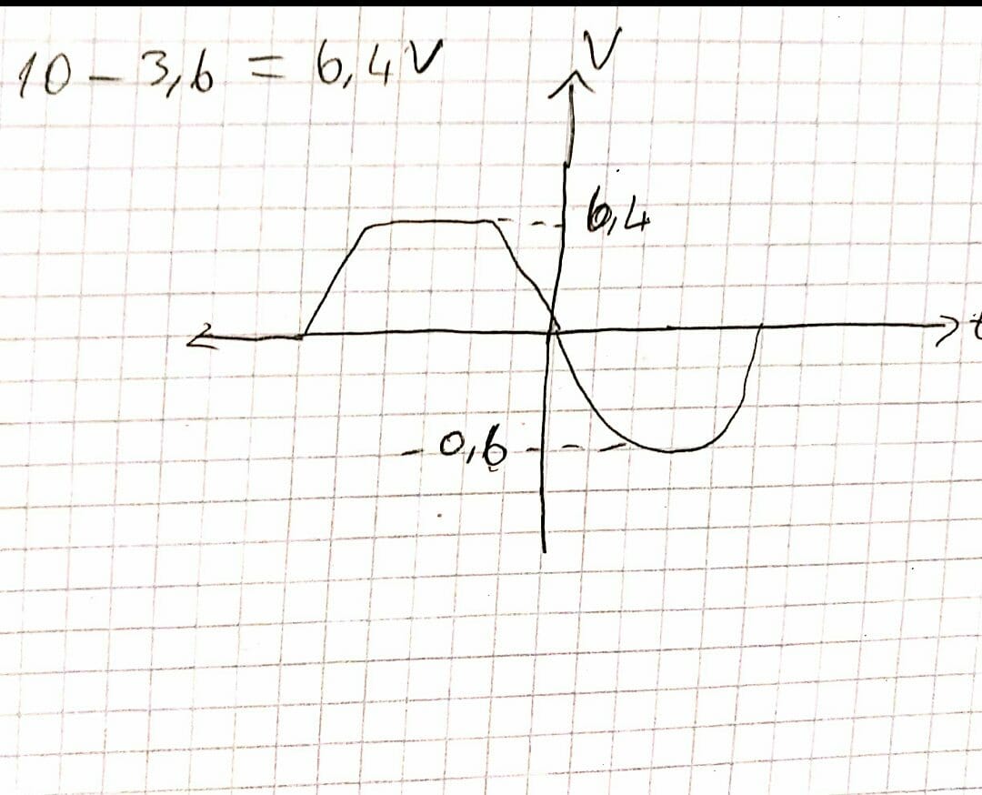
if we don't calculate the resistors. Could the output signal be this way?enter image description here
\$\endgroup\$
8
  • 2
    \$\begingroup\$ In your 'simple' circuit Vo = Vi, no matter what is between them. It's not at all like the original. \$\endgroup\$ Commented Jun 5, 2020 at 1:58
  • \$\begingroup\$ IN your hand drawn schematic Vo = Vi. The diodes and resistors don't do anything. \$\endgroup\$ Commented Jun 5, 2020 at 1:58
  • \$\begingroup\$ can you help for the truth? \$\endgroup\$
    – safak26
    Commented Jun 5, 2020 at 2:03
  • \$\begingroup\$ @safak26 More like this, perhaps? \$\endgroup\$
    – jonk
    Commented Jun 5, 2020 at 2:23
  • 1
    \$\begingroup\$ @safak26 You should be able to just look at it and work out the output. When the signal goes high, it has to drop through one diode (the other is blocking) and overcome 3 V (so 3.6 V total) before it can appear at the output. So that one will be (10-3.6)=6.4 V peak. From 0 V to 3.6 V, it is clipped. On the other half cycle it has to drop through the other diode, 0.6 V, and then experiences a 1/3 resistor divider, so it peaks at 1/3 * 9.4 V or about 3.1V. From 0 V to -0.6V, it is clipped. A double-bump with shoulders, kind of. \$\endgroup\$
    – jonk
    Commented Jun 5, 2020 at 2:36

0

Your Answer

By clicking “Post Your Answer”, you agree to our terms of service and acknowledge you have read our privacy policy.

Browse other questions tagged or ask your own question.