There are several possible causes.
The current loop formed by the batteries and motors is a big electromagnet. Every time motor current rises or falls, that loop's changing magnetic field couples to absolutely every other loop nearby. That includes every signal line in the vicinity, such as the reset line of your MCU. There are some things you must do to minimise this coupling.
Concerning the loop formed by the batteries, motors and associated wiring, Keep the physical loop area as small as possible. To that end, keep all conductors as close as possible to each other. Keep this loop as physically distant as possible from other stuff, and certainly keep other stuff physically outside of that loop.
Motor wiring, between the L298 and the motors themselves is also critical, for the same reasons. Keep loop area low by twisting the cables together, or at least keeping them running parallel and close together.
Ensure that power supply decoupling for the motor section is as close to the point where current switching occurs, that is, the L298. Use a large electrolytic capacitor, and a smaller ceramic capacitor across the power supply to the L298. They will accommodate sudden increases and decreases in current demand, being a power source more local to the L298. This will dampen the rising and falling of current in the wiring between the batteries and L298, and mitigate magnetic coupling to other nearby elements.
Power supply decoupling for other elements in your system is also essential. Use a ceramic capacitor (whose value will depend of the current requirements of the element, but 100nF is typical) across the supply rails for every element in the circuit. Decoupling provides a more local voltage/current source, with two consequences. Firstly the element being decoupled is somewhat protected from the changing current demands of the rest of the system. Secondly that same decoupling protects the rest of the system from whatever crap this particular element spits out onto the supply.
If these two approaches are not sufficient, one more thing to consider is that the 7805 is terrible at preventing fast transients at its input (which may result from motor current switching) from getting through to its output. You may have to filter the input to the 7805, to attenuate transients before they even get to that regulator. Your options include:
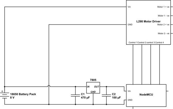
Better capacitive decoupling at the regulator input. A single ceramic 1μF capacitor physically close to the regulator, between IN and GND could be all you need (in addition to the 470μF one you already have).
An inductor between the batteries and regulator input, to suppress fast current transients.
A capacitiance multiplier in parallel with the physical 470μF capacitor, both of which should be very close to the regulator, between IN and GND.
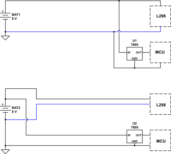
(Edit) Don't share long wires from the battery between the MCU side and the motor side. Those wires will carry lots of current, or very little, and the fluctuating voltage drop along them can give the 7805 a hard time. The following look the same, but in the second circuit, the low current stuff has its own supply cabling right up to the battery, relieving the 7805 of a lot of work:

simulate this circuit – Schematic created using CircuitLab
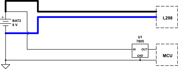
While this setup better isolates the supplies for the two sections, it introduces another complication, which is that the L298 and MCU may have different ideas of what 0V (ground) is. There can be a lot of current through the blue wire, and a corresponding voltage drop along it, which separates the ground potentials of the two systems.
One way to mitigate this is to use a really beefy ground conductor (and while you're at it, may as well beef up the other motor wire, too), to minimise the voltage it drops while passing all that current:

simulate this circuit
Really this is all just a communication issue, between the MCU and L298, which you might not even suffer from, and isn't directly related to your MCU "resetting" or "crashing". Just make sure your cables carrying motor current are heavy enough, and routed properly, and be aware that the signaling levels between the MCU and the L298 can get messed up if grounding is poor.
- Less likely, but maybe your motors are horribly noisy, electromagnetically, enough to mess with Wifi and a few other things. If you have DC motors with brushes, try connecting a 100nF capacitor from each motor connector to the motor casing, and the motor casing to circuit ground (check that the casing is isolated from both terminals first, to avoid a short circuit). Another check might be to encase all the MCU stuff in a metallic enclosure, connected to circuit ground. Take care with short circuits again. That might upset Wifi to the MCU, but if your MCU stays alive and well, at least you know you have an EMI issue.


