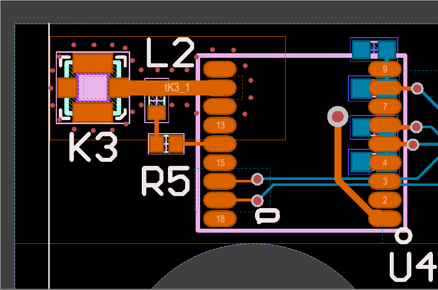
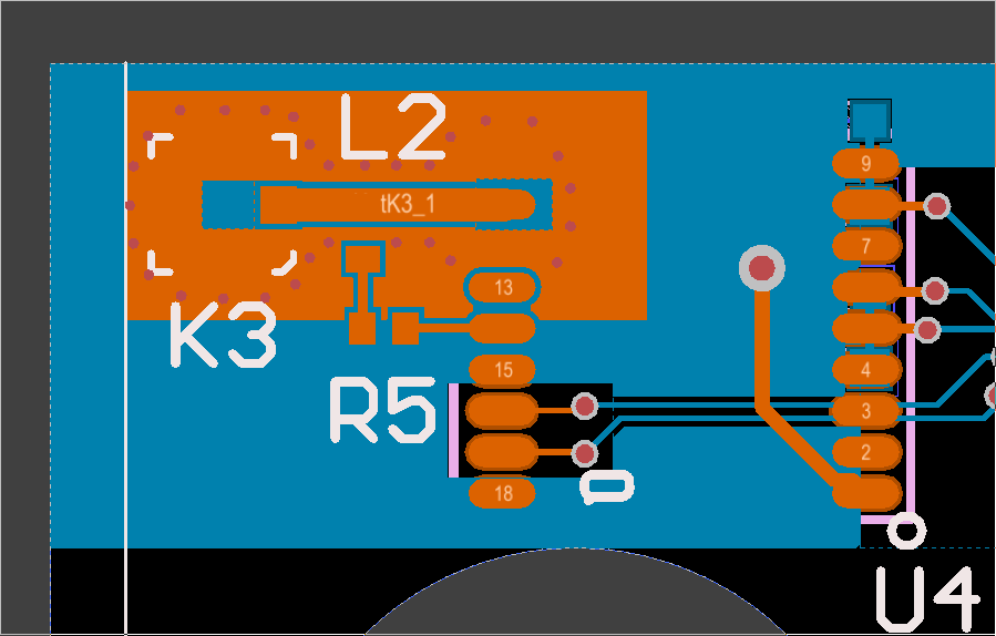
I am having trouble with the reception of my GPS module - a Quectel L76L. I am connecting the Antenna via a U.Fl connector. I know that the issue is somehow due to my layout because it works on a breakout board that I purchased (which used a chip antenna), but not the PCB I made. I’ve tried a whole bunch of things but none seem to work well. It takes well over 10 minutes to get fixed, and another 10 - infinity minutes to get readings. something is definitely not right.
Things I’ve kept in mind:
- Transmission line - keeping the trace length below .25in
- Vias - both many vids all around the signal for the coplanar waveguide and more sparse.
- Trace width - I’ve used the calculated 50 ohm impedance of 42.2 mil and the 35 mil width that the GPS spec sheet recommends - Since the trace width is larger than the pad, which width should I use? I saw a video recommend to use a trace width as large as possible to match the chip’s pad (this would be 31 mil).
- Using active antenna, so I am using a 10Ohm resistor and a 47nF inductor
Please see the layout below that did not work.. is there anything wrong that is glaringly obvious? Is it okay that I put the inductor pad on the micro strip?
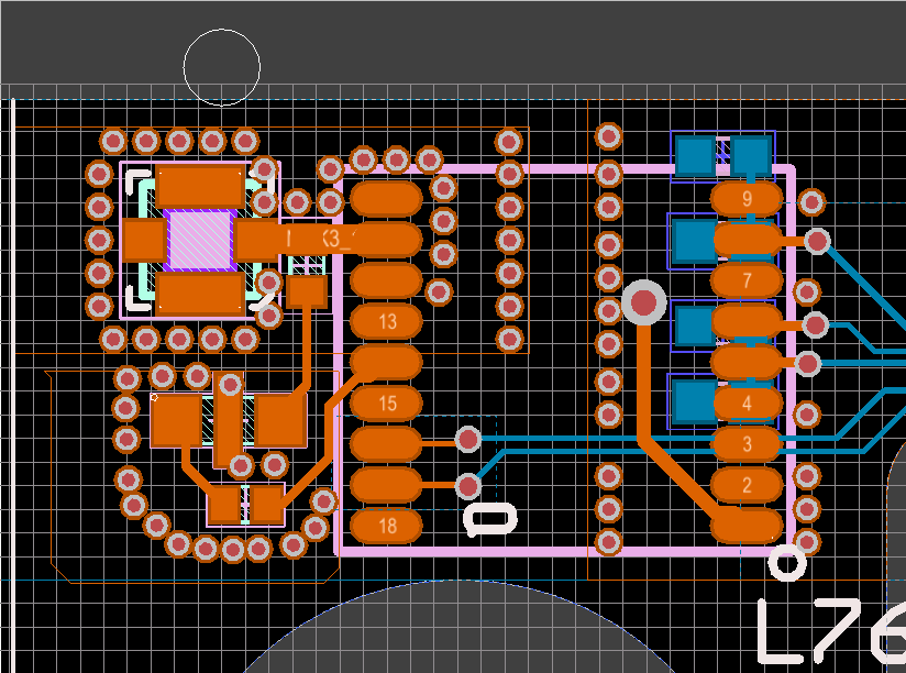
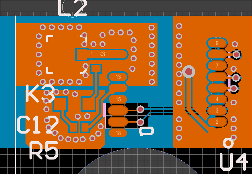
Also, please see this design which I plan to send in for FAB. On this one I brought the antenna way closer to the GPS unit, I reduced the trace width to match the pad width of the GPS unit (31 mil), and added a bunch of bias that are a bit bigger. I also added a passthrough capacitor.
Does this design look like it will work? After about 6 iterations, I am at a loss of what could be the issue... Any advice will be much appreciated.


