0
\$\begingroup\$

This is my ISELED Driver Datasheet INLC10AQ & my Microcontroller datasheet S32K142 - 64 pin Microcontroller

I have a NXP Microcontroller connected to the above LED Driver. I need to figure of the type of protocol that is used for the uC communication and the LED Driver.

In the first page, 3 paragraph of the product description, it is mentioned like " A proprietary bus protocol is used" and in first page, features section the datasheet mentions "Bidirectional, half-duplex, 2Mbps, CRC protected serial communication"

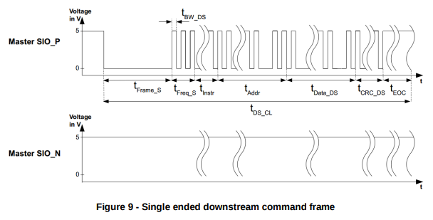
It is also mentioned that the communication between the uC and the first LED Driver is single ended. The type of serial communication between the uC and the driver is given in, Figure 9 - "Single ended downstream command frame"

My questions :

  1. My uC pin has LPSPI module , FlexIO module, FTM Module & GPIO module capacbility. Which module module usage will help me with the communication between the uC and the pin 7 & 8 of the LED Driver.
  • My thinking is, since the serial protocol is used for the communication and the pull-up is required for the communication lines, may be FLEXIO module must be used at the uC pins. Or can the protocol communication be established just by using GPIO module at the pins and perform bit banging?
  1. Is the single ended serial communication between the uC and the LED Driver one-way communication (simplex)? Because no Voh values for single ended serial communication is not provided in the LED Driver IC datasheet. Why is that?
  • But in the first page, features section, it is mentioned as bidirectional half-duplex serial communication. So, there must be communication between the LED Driver and the uC, right? If then, What value of Voh should I consider for the single ended serial communication?
\$\endgroup\$

1 Answer 1

1
\$\begingroup\$

At the electrical level, the protocol used for single-ended mode looks a lot like I²C or 1-wire with the lines being pulled normally-high. You could bit-bang this protocol or (if you need better performance) you could use the microcontroller's FLEXIO functionality. As shown in the INLC10AQ datasheet starting from page 12, the protocol for single-ended mode is as follows:

  • The microcontroller holds the SIO_N line high1 to indicate single-ended mode then writes output bits to the SIO_P line by driving the line low. The signal is self-clocking. This is shown on page 12 of the datasheet:
    Microcontroller transmit signalling

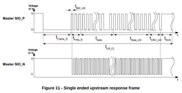
  • When done sending the microntroller switches its IO pins to be inputs and the SIO_P and SIO_N lines are pulled high by the pull-up resistors. To send a response, the peripheral chips drive the SIO_P line low to indicate 0 bits while at the same time providing a clock signal by driving SIO_N low. This is shown on page 14:
    Peripheral response signalling

    Since the high and low voltages on the SIO_P and SIO_N lines are the same as the microcontroller's GPIO voltages (as elaborated on below), simple digital reads of the GPIO port values can be used to read the serial data stream sent from the LED modules2.

For single-ended operation the VIL,SE and VIH,SE are given on page 8 of the datasheet:

IO voltages as shown in the datasheet

Since the parameters are from the perspective of the peripheral chip (the INLC10AQ) they are given as input voltages, not output voltages (i.e. as VIL,SE and VIH,SE rather than VOL,SE and VOL,SE). On the microcontroller end you'll need to bring the voltage down to 1.04V or lower to send a 0 bit or pull it up to between 1.08V and 5.5V3 to send a 1 bit. Likewise, the peripheral INLC10AQ will connect a line to GND to indicate a 0 or leave it pulled high to indicate a 1 (the peripheral never actively drives a line high; it goes high-impedance to indicate a 1). Per the recommended circuits shown in the datasheet (p. 27) the recommended value for the pull-up resistors is 1kΩ 4 with a maximum trace length of 15cm between the microcontroller and the first INLC10AQ5.


In a nutshell, the INLC10AQ uses a proprietary communications protocol whose electrical characteristics are described above. The low and high input and output voltages are the same as those used by the microcontroller. Typically these voltages are 0V for a 0 and 5V for a 1 though a lower signalling voltage (e.g. 3.3V or 1.8V) can be used for the latter. No VOH or VOL values are given in the datasheet for single-ended mode because the line voltages are provided at the microcontroller end (VDD via pull-up and ground, respectively), not by the INLC10AQ.


1 Ideally, the microcontroller should leave SIO_N high-impedance (i.e. as an input). The pull-up resistor will ensure that the line is normally high.

2 One will, of course, need to decode the serial bitstream either manually or by using FLEXIO.

3 The datasheet lists 5.5V as the maximum recommended high voltage (VCC5); 7V is the absolute maximum.

4 There should be two pull-up resistors: one between SIO_P and the microcontroller's VDD line and the other between SIO_N and VDD.

5 Per the ISELED FAQ.

\$\endgroup\$

Your Answer

By clicking “Post Your Answer”, you agree to our terms of service and acknowledge you have read our privacy policy.