2
\$\begingroup\$

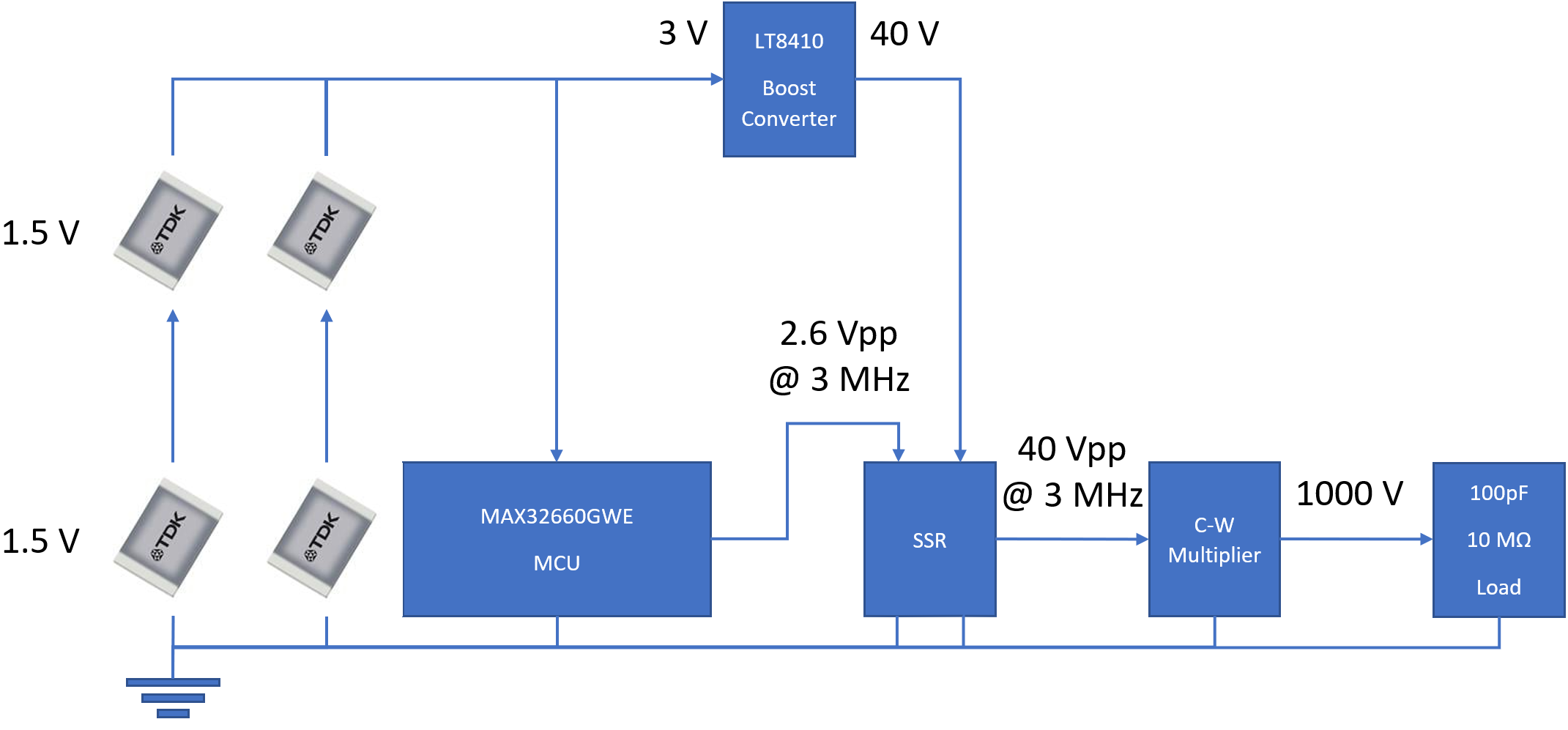
I could only find one question semi-relatable to mine on SE, but I have a more demanding application in mind. I have designed a 32 stage 40 VAC -> 1000 VDC Cockroft-Walton voltage multiplier which I plan to drive with the 2.6 VAC clock from my MCU. To get my SMD capacitor sizes submillimeter, I have to run the clock at over 3 MHz...

My plan was to use a LT8410 to boost my battery's 3 VDC to 40 VDC and switch that w/ the clock through an optocoupled solid state relay:

circuit diagram

I went with this topology bc I read somewhere that SSRs "have fast switching speeds which can range from 1 to 100 nanoseconds" but the smallest \$t_{\text{ON}}\$ (Turn-ON time) I've found was 500 ns & I need less than 50 ns to obtain an acceptable square wave at 3 MHz.

So is it even possible for an SSR to switch this fast or should I have went with a different topology to deliver the 1000 V?

\$\endgroup\$
14
  • 1
    \$\begingroup\$ have fast switching speeds which can range from 1 to 100 nanoseconds My opinion: whoever wrote that article has no clue. SSRs are generally used for mains switching which is 50 or 60 Hz, so there is no need for ns response times. What could be the case is that the transition from off to on of the SSR is in the 1 to 100 ns range. That doesn't mean it can be switched on/off in a few ns. TLDR: an SSR isn't going to work in this application. \$\endgroup\$ Commented Jun 19, 2020 at 8:15
  • 1
    \$\begingroup\$ I also think that your system isn't what I would choose. I would use a transformer to boost 3 V directly up to 500 V and then double that or go directly from 3 V to 1000 V. A CW multiplier can work but in my view not with the amount of power that you need and so many stages in series. The losses in each stage will prevent you from reaching the 1000 V. I also suggest that you study other high voltage generators and see what is commonly used. "Designing your own" only works if you have enough experience of what works and what doesn't. Also: some solutions work in theory but not in practice. \$\endgroup\$ Commented Jun 19, 2020 at 8:22
  • 3
    \$\begingroup\$ XY problem. The op is trying to shoe-horn something in that is not fit for purpose. \$\endgroup\$
    – Andy aka
    Commented Jun 19, 2020 at 8:38
  • 1
    \$\begingroup\$ 3 volts to around 10 kV \$\endgroup\$
    – Andy aka
    Commented Jun 19, 2020 at 8:42
  • 2
    \$\begingroup\$ All of my components have to fit on a cm^2 board to meet project requirements Not the first time that "a customer" asks for the impossible. That's why you need proof of what can and cannot be done. That's where an architecture study comes in. A starting point is to investigate similar designs, what is used there? What size are they? Why is that so? A customer can easily write down anything that they want, small size, small cost etc. That doesn't mean that what they ask is possible. \$\endgroup\$ Commented Jun 19, 2020 at 9:26

1 Answer 1

2
\$\begingroup\$

So is it even possible for an SSR to switch this fast or should I have went with a different topology to deliver the 1000 V?

The design of solid state relays often prevent this. In order to not consume much energy when off they disable the booster required for the high side switching.

You can do this yourself with a high side gate driver and N-channel mosfet. Eg: 1EDN7550.

\$\endgroup\$
2
  • \$\begingroup\$ I would probably just stick with an N channel driving a P channel, rather than a whole gate driver \$\endgroup\$
    – BeB00
    Commented Jun 19, 2020 at 17:28
  • \$\begingroup\$ The boost converter I'm using has a disconnect switch that I could use when not active. \$\endgroup\$
    – Landon
    Commented Jun 19, 2020 at 19:34

Your Answer

By clicking “Post Your Answer”, you agree to our terms of service and acknowledge you have read our privacy policy.

Not the answer you're looking for? Browse other questions tagged or ask your own question.