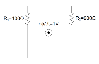
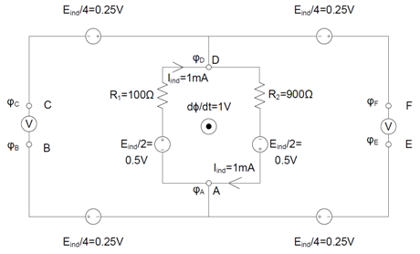
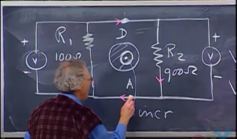
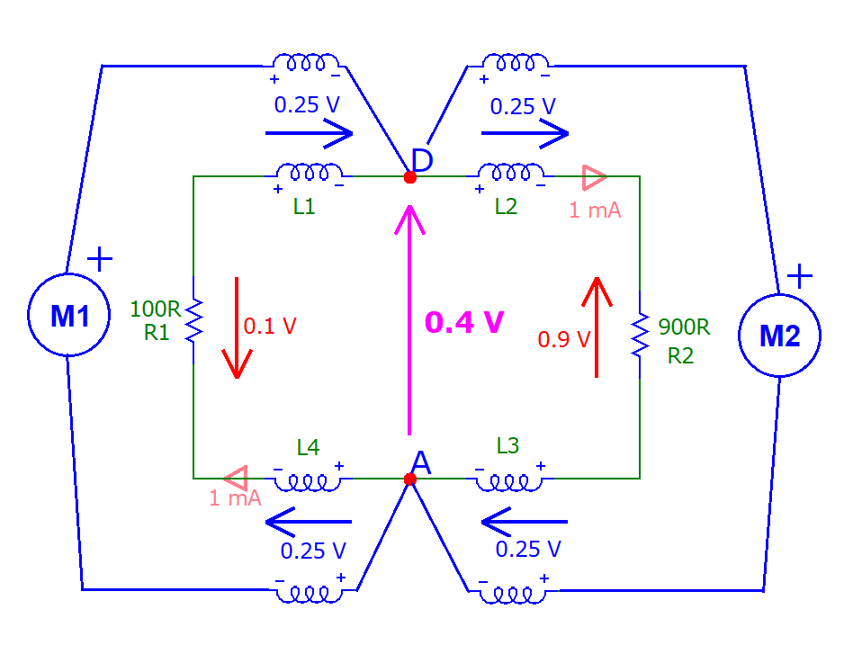
YES, two voltmeters connected to the very same couple of terminals can simultaneously show two different values.
The reason is that, since the circuit path is enclosing a variable magnetic flux region, the 'theoretical potential difference' between point D and A is not (uniquely) defined.
Actually, that's all there is to it.
Because if your circuit sits in a variable magnetic field region, then all the paths between nodes sit in a dB/dt region, and since the line integral of the electric field along any closed path will not always be zero (this is basic physics), it is not possible to define a potential function such that the line integral of E from D to A only depends on the values in D and A. It will depend on the path.
(This is basic calculus)
Since this notion usually encounters a certain resistance to be accepted, it is worth to have a deeper look at where it comes from and what it entails in detail. Answering to all the doubts that emerged from the numerous internet interactions after Walter Lewin made his 'superdemo' accessible to the masses, requires a lot of space. For the TL;DR people, the rest of this post is structured in this way:
- A definition of potential difference
Where we define what is usually meant for voltage in circuit theory and why you can reduce it to a potential difference (hint: the irrotationality of the electric field makes voltage a function of the endpoints only)
- Lumped Circuit Theory I : Kirchhoff rulez
Where we see what physical condition makes it possible to have an irrotational E field and make use of the concept of voltage as potential difference. (Hint: it's the absence of a varying magnetic flux: Kirchhoff's Voltage Law is just Faraday's law when dphi/dt = 0)
- Lumped circuit theory II : Limited regions of non-conservativeness outside the circuit's path
Where we try to save KVL by hiding circumscribed regions of variable magnetic flux inside the magnetic components (note: this is what Lewin refers as the stinky physics of 'taking the right hand side on the left side' and what I call 'new KVL' or 'amended KVL': if the circuit path does not enclose a variable magnetic field, we can pretend there is a unique voltage expressible as potential difference by simply not looking inside the magnetic components)
- The Romer-Lewin ring, or: the unlumpable circuit
Where we see that when the circuit path encloses a variable magnetic flux KVL is no longer salvageable, and voltage in your circuit becomes path dependent (which means: it is no longer possible to express it as potential difference)
- Scalar and Vector Potentials
Where we take a look at an alternative definition of voltage that admit a scalar potential. (hint: this is what I call the McDonald maneuver, and it entails separating the total electric field into two constituents parts, one conservative that is caused by coulombian interaction, one rotational that is caused by magnetic induction)
- The role of surface charges
Where we look at what makes the total field in the conductor and the resistors the way it is.
- The concept of partial inductance
Where we take a look at how trying to model the induced voltage with partial lumped 'secondary' coils corresponds to a different physical situation and how partial inductances can be used (with due caution) as a tool in the field of electromagnetic compatibility
.
1 - A definition of potential difference
When you define voltage as the potential difference between two points
VBA = VB - VA = Vab (going from a to b)
you are implicitly assuming that - apart from an additive constant - the potential function is uniquely determined, that is the (negative of the) path integral of the electric field from a to b

does not depend on the particular integration path chosen integration. This situation requires that the electric field E be conservative or, and this name is telling, irrotational.
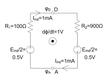
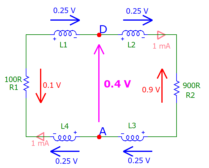
If the electric field is made rotational, as it happens in the presence of a variable magnetic field, then you can get different results at once for Vab, depending on the particular path you choose to compute the integral: you go along the path that passes through R1, you get 0.9V; you go along the path that passes through R2 you get -0.1V; you go along an arbitrary path that follows Snoopy's profile in and out of the conductor and resistors, you get 0.741V, you name it. (Note that I am not mentioning probes at all.) The endpoints alone are no longer sufficient to uniquely determine the voltage.
Here's the disambiguation between the two conventions I am going to use. Since it would be too much to use a different letter to denote path-dependent and path-independent voltage, I will use V for both, leaving it to the smalltext to tell them apart. So, Vab stands for

and it's the energy per unit charge required to go from point A to point B along the path gamma(a->b). l will denote this, generally path-dependent , voltage with Vab, with lower case letters from start point to endpoint.
When the electric field is irrotational, there is a potential function V such that

so that the line integral becomes path-independent and only the endpoints A and B needs to be specified, not the path gamma joining them (any path will do).

I will call this voltage 'potential difference' and will denote it with VBA, with capital letters ordered from endpoint to start point. Note: the endpoint comes first, since I adopt the convention VBA = VB - VA (graphically represented with an arrow going from A to B). This will further help in differentiate between the two.
A little digression
There really is nothing strange in having line integrals dependent on path, in fact it's conservative fields that are almost magically special. In the real world it is normal to consider a function computed by integration along a path to depend on the particular path itself and not on its endpoints alone.
Consider the energy spent to reach the top of a mountain in your car from the same parking lot and let's measure it in gallons of gasoline: if you choose a straight path you need 10 gallons, if you choose a loose spiral you need 20 gallon, a loose spiral against the wind and it's 25 gallons, but if it's along with the wind it's 18 gallon; a wobbly path with backs and forth and it's 35 gallons. (It's a very high mountain, mind you).
Would you find it strange if the answer to "what is the theoretical gasoline consumption for going from A to B?" was "it depends"? Of course not, you would be surprised of the contrary. (And yet you could think of a minimum consumption that could be thought of as 'unique', I get back to that later, when I introduce the vector potential).
Also, would you expect your gas tank to refill itself by simply going down to the parking lot? I believe you would be very much surprised if that happened. And yet, that's what happens with conservative fields: going full circle will give you a zero line integral. They are the counterintuitive stuff, not the other way around.
2 - Lumped Circuit Theory I : Kirchhoff rulez
Lumped circuit theory is so easy because it is based on this special, almost magical, kind of fields. The theory is so simple and beautiful that many engineers cannot let go of it and try to use it even when it is not applicable.
The fundamental assumption of lumped circuit theory is that you must be able to define voltage between two points independently of the path. Considered the definition of voltage given above this means that

and in particular, if we choose a closed path of integration, i.e. a=b, the circulation of E must be zero

It turns out that having zero circulation for the electric field along any closed path is a necessary and sufficient condition for the existence of a potential function. Now, since one of the fundamentals laws of physics, Faraday's law, states that

it follows that if we want to be able to express voltage as a path independent potential difference, we must avoid regions of changing magnetic flux. Feynman is very clear about this in his Lectures: Volume II, Ch. 22, "AC Circuits" (emphasis mine.)
Suppose we have a circuit consisting of a generator and several
impedances connected together, as shown in Fig. 22–9. According to our
approximations there is no magnetic field in the region outside the
individual circuit elements.
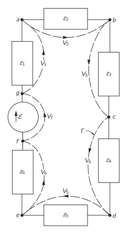
Therefore the line integral of E around any curve which does not pass
through any of the elements is zero. Consider then the curve Γ shown
by the broken line which goes all the way around the circuit in
Fig. 22–9. The line integral of E around this curve is made up of
several pieces. Each piece is the line integral from one terminal of a
circuit element to the other. This line integral we have called the
voltage drop across the circuit element. The complete line integral is
then just the sum of the voltage drops across all of the elements in
the circuit:

Since the line integral is zero, we have that the sum of the potential
differences around a complete loop of a circuit is equal to zero:

This result follows from one of Maxwell’s equations—that in a region
where there are no magnetic fields the line integral of E around any
complete loop is zero.
So, KVL is just a particular special case of Faraday's law, when the electric field behaves in that magical way that will refill your gas tank when you go from the top of the mountain back to the parking lot.
If your circuit path encloses a varying magnetic field then you are out of luck: the voltages in your circuit will not have unique values for the same endpoints but will also depend on the particular path along which you compute the line integral.
But notice that Feynman says:
"According to our approximations there is no magnetic field in the region outside the individual circuit elements."
So, there is room for some magnetic field madness, it seems. Well, within reason.
3 - Lumped circuit theory II : Limited regions of nonconservativeness outside the circuit's path
If we were to completely avoid regions of varying magnetic (and displacement) field, we would be stuck with simply resistive circuits. Let's see if we can work out a solution that allows for dynamic elements such as inductors (and capacitors) into the picture without giving up the simple tools represented by KVL (and KCL). Turns out we can, if we add the extra proviso that all the variable field craziness be left outside of the circuit path by confining it inside lumped components.
Leaving the variable magnetic region outside the circuit's path will allow us to define voltages in the circuit in an unique manner and use Kirchhoff laws to compute voltages and currents as we did with resistive circuits. By hiding the complexity of variable magnetic (and electric fields) inside the dynamic components, we can pretend that the voltage across them and the current through them still obey Kirchhoff rules, while in fact, deep inside, they are determined by the more general laws of Faraday-Neumann and Ampere-Maxwell.
Let's consider the following circuit, with a generator, a resistor, an inductor, and a capacitor along the path that connects all their terminals together:
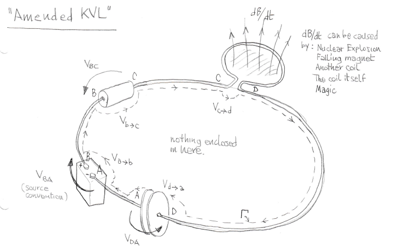
The variable magnetic field regions are indicated by shaded regions and are relegated inside the magnetic element. The closed path can be decomposed into the following segments:

Now, if - as it happens in this picture - the circuit's path does not enclose a variable magnetic field region, we can write the path integral of the electric field across the closed loop a-b-c-d-a and rest assured it is zero. This is the condition required to consider voltages function of the endpoints only, and for KVL to work (sum of voltages along a closed circuit is zero).
KVL works because, by not enclosing any variable magnetic field in our circuit path Gamma, all voltages can be considered path-independent and it does not matter how we integrate from one terminal to the other.
But are all voltages in this circuit really all path-independent? Well, no. We just pretend they are by turning a blind eye at those that are not.
It turns out that when we come across the magnetic component, we can choose paths that go from one terminal to the other by entering or encircling the variable magnetic flux region. The voltage computed as a line integral along those paths will in general be path-dependent.
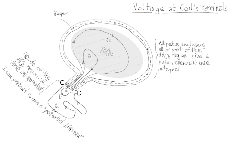 Not all paths going from one terminal to the other give the same result, if we go inside the component
We can have paths from C to D crossing the region of variable magnetic field so that there are closed loops passing from C and D whose line integral is not zero. This means that we can have multiple values for the voltage between C and D. In particular there are different values for the line integral going from point C to point D in the space between terminal (say a voltage V) and another, different, value for the line integral along the path that follow the coil inside the conductor (and that value is zero).
There is hope, though. Among the infinite number of paths to choose from, those that do not go inside or around the forbidden region (like those indicated by \$\gamma_1\$, \$\gamma_2\$, and \$\gamma_3\$) all give the same result (in fact, by choosing them we always end up with an overall circuit path that will not enclose the magnetic variable region.)
So, if when we consider a path connecting the terminals we are smart enough to stay clear of the variable magnetic flux region, our circuit path will be in the clear, and - if we can delude ourselves that the coil voltage only depends on the endpoints (it does not!) - we will be able to use a mock-up version of KVL (much in the same way that jumping at the capacitor's terminals we can use a mock-up version of KCL)
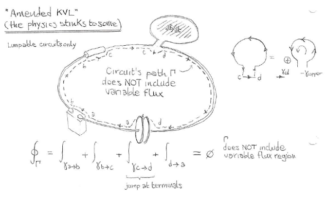
Now, the problem is to find what is that one value of the path integral along any 'safe' path that goes from one terminal to the other without going inside or around the forbidden zone of the magnetic element. It turns out we can easily compute it by using - you guessed it - Faraday's law.
The fake 'potential difference' across a coil
We are going to consider this part of the circuit where we the value of \$B(t)\$ or \$\Phi(t)\$ is determined by the effects of a nuclear explosion, a falling magnet, another coil or even elven magic (but note that I am not considering the case of a moving coil - meaning we are in a frame of reference where the coil CD is at rest)
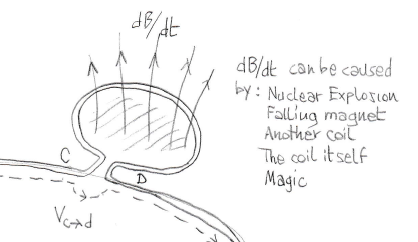
We are interested in the line integral along one of the 'safe' paths from C to D, that we will call \$\gamma_{term}\$. We can easily compute it considering it as part of a closed loop that encircles the variable flux region by going through the copper (so that the electric field has a known or easy to compute value and direction)
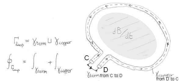
We can split the closed loop line integral into its constituent parts i.e. the path that connects the terminals from C to D (\$\gamma_{term}\$), and the path that goes through copper from D to C (\$\gamma_{copper}\$):

what we are interested in is the fist integral on the right hand side, that corresponds to the mock-up 'potential difference' at the coil terminals. We can find it right away considering that the circulation of the electric field across the closed loop has a value given by Faraday's law, and that the line integral going through the copper is zero because the electric field inside a stationary perfect conductor - even under the effect of induction - is zero:
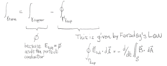
and here is the result for our mock-up 'potential difference':

I put "VDC" in quotes because it is not a real potential difference, since in general this voltage depends on the path and not only on the endpoints C and D. But if we can make sure that we refer it to paths that do not get into or around the inductor's guts, we can pretend it is single-valued.
The voltage you see at the terminals of the inductor is the time derivative of the magnetic flux phi. The sign of the voltage depends on the orientation of the magnetic field and on how it is changing (decreasing, increasing) If you want, add that \$\Phi = L * i\$ (and in that case, since the magnetic flux is produced by the current in the loop itself, the sign of the voltage will follow from Lenz's law) or \$\Phi = M * i\$ (here the sign also depend on how you orient the coils) and you get the well known relations for self and mutual inductance. But this result is also valid for magnetic field changes caused by a falling magnet or a nuclear explosion.
Zero field in the conductor means no voltage build up inside the coil
Now, what it most interesting to us is that, despite the voltage presented at the terminals, the (total) electric field inside the copper conductor the coil is made of is zero. There is no 'incremental voltage build up' so to speak. All voltage appears at the terminals. This is how Ramo, Whinnery, and VanDuzer put it (p. 171 in the 2nd edition, emphasis mine)
"The voltage at the terminals of the magnetic element comes from the
time rate of change of magnetic flux within the inductor, shown in the
figure as coil. Assuming first that resistance of the conductor of the
coil is negligible, let us take a closed line integral of electric
field along the conductor of the coil, returning by the path across
the terminals, fig. 4.2b. Since the contribution along the part of the
path that follows the conductor is zero, all the voltage appears
across the terminals."
How is it possible to have the path integral of the (total, see later expansion) electric field E be zero inside the coil's conductor, when we can measure a voltage at its terminals? Well, much like in the case of electrostatic induction, the charge that produces the field outside the copper is the very same charge responsible for making it zero inside the copper. In the electrostatic case the path integral is zero both inside and outside the conductor; in the quasi-static case of induction in a stationary conductor, the path integral is zero inside but non-zero outside.
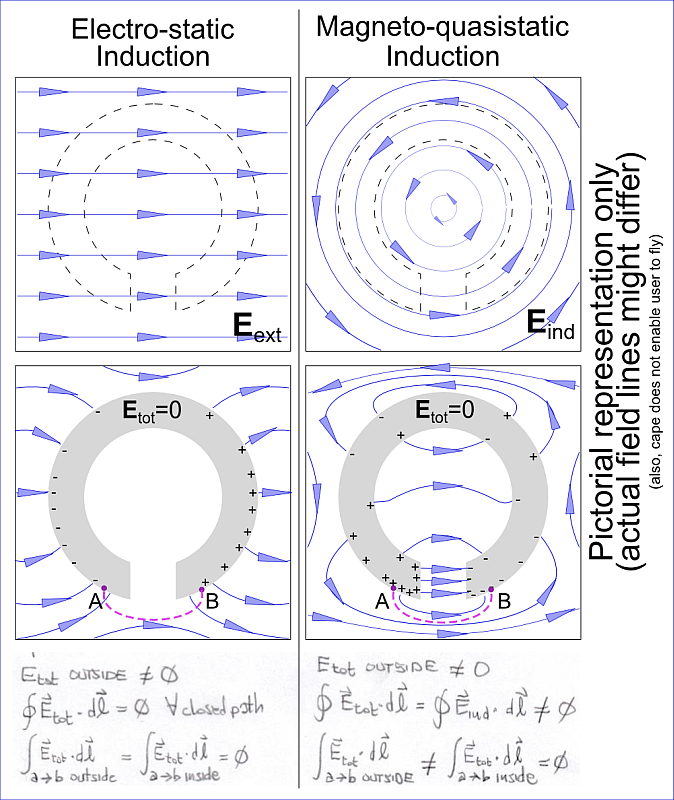
If you compute the line integral of the electric field jumping along a safe path from one terminal to the other, you get nonzero values (corresponding to the voltage that is given by the time derivative of the magnetic flux) because there is an overall non-conservative electric field in the space between the terminals, but if you compute the line integral from the same two endpoints by going inside the conductor, you get zero because inside the perfect conductor in these quasi-static conditions there is no electric field.
So, there you have it: multiple values for the voltage between the same two points in all your circuits using any form of inductor.
The trick we use in circuit theory is just to pretend not to see the infinitely many values the line integral can have if we choose paths inside the component's forbidden region, and only look at the nice paths outside of it that consistently give the same value. By forgetting that it is only one value among many, we call that voltage a 'potential difference' even if there is no potential function.
Now, if you were to make voltage measurements in your circuit you would get consistent results, no matter the path you choose as long as you stay out and do not go around the forbidden region inside the magnetic component. It is with this proviso that we can pretend we can still talk about path-independent voltages and potential differences. The working of your circuit is based on that illusory 'unique' voltage at the inductor's terminals.
But if you put your probes around or inside the magnetic component, you will commit a probing error, because messing with the forbidden region will destroy that illusion.
Sneak preview: Why can't the 'amended KVL' work in the Romer-Lewin ring?
The Romer-Lewin ring has some points in common with the above lumped circuit, but also some striking differences.
Similarly to the circuit with an inductor, there is no total electric field inside the conductor, and all the E field end up between the resistors (or non-magnetic components) terminals.
The really big difference is that now it's the circuit path that encircles a variable magnetic flux region, hence we are always inside the 'forbidden region' where KVL does not work and we cannot 'stay out' of it like we did in the case of the isolated magnetic component. Since in general the line integral of the total electric field along any closed loop will not be zero but equal to minus the time derivative of the magnetic flux enclosed by the path, we cannot have a potential function. Voltages in the circuit will in general be path-dependent, and we have to expect multiple values for the voltage between two points.
This multivaluedness of voltage is not the result of a measurement error, it is just a consequence of the fact that all the circuit sits in (encircles) the forbidden zone, and thus KVL, not even the 'amended' one, cannot work there. You cannot take two terminals out and put them in a 'safe' circuit path the does not go around the forbidden zone, as we did for the lumped inductor in the previous circuit.
Moreover, if you were to subtract the effects of induction thinking this is what good probing is about, you would commit a probing error. You will end up measuring a voltage that does not correspond to the actual configuration of electric field in the circuit but correspond instead to only a part of it (this is shown in part 5 where the induced field is subtracted the total field).
What is the "5 + 3 = 8 is not 5 + 3 - 8 = 0" all about?
Had we chosen to go from one terminal of the inductor to the other following the conductor, we would have had to abandon KVL and resort to the more general Faraday's law, because the new overall circuit path would be enclosing a variable magnetic field:
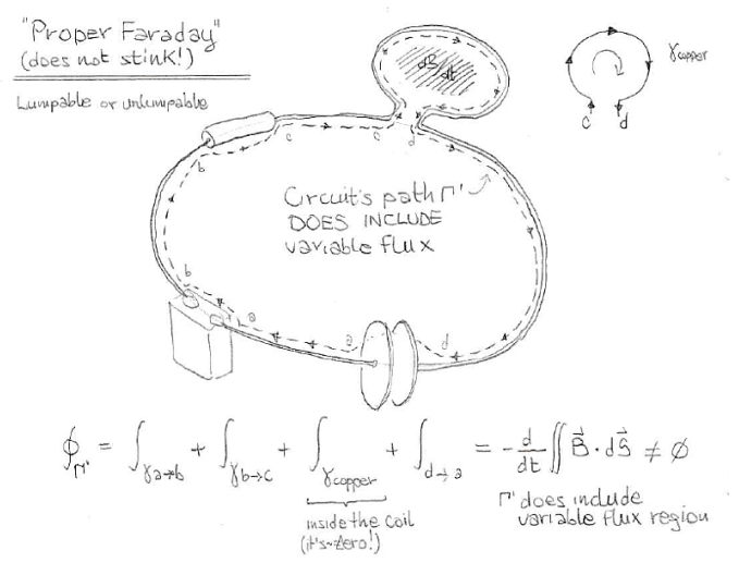
And this is the right way to treat problems with changing magnetic flux: 5 + 3 = 8. It does not pretend that the voltage be path-independent (it isn't) and makes the contribution of the magnetic flux explicit in the right hand side of the equation.
But if we are desperate to see our beloved KVL again, we can take the right hand side term to the left hand side, and we end up with 5 + 3 - 8 = 0, the 'amended version' of KVL, where the mock-up inductor voltage is the time derivative of the magnetic flux.
This is convenient, because we can pretend KVL still works, but it is also misleading because it makes it seem that the voltage is path-independent when in fact it isn't.
4 - The Romer-Lewin ring
In the Romer-Lewin ring two (lumped) resistors are placed inside a coil enclosing a variable flux region so that the circuit's path encloses a dB/dt region. Feynman is adamant: you cannot use lumped circuit theory. Lewin is also adamant: you cannot use Kirchhoff's law (it's for the birds!), so we need to go back to the more general relation: Faraday's Law.
If you accept that the variable B field will generate a rotational E field, things can be explained by looking at how charges in the circuit react to the induced field, change their configuration and produce a different resulting electric field inside and nearby the ring.
If you were to magically make the ring made of copper conductor and two resistors appear inside this circulating field, the charges inside and on the surface of its parts would almost instantaneously redistribute themselves in such a way as to obey Ohm's law.
We can get a glimpse of what drives the charge redistribution by considering the continuity equation.
Charge displacement - gradients in charge density \$\rho\$ - happens on the surface also in the longitudinal direction, anywhere there be gradients in the values of conductivity and permeability. If we assume \$\frac{\partial \rho}{\partial t}=0\$, then the continuity equation becomes div j = 0 and by adding compliance to Ohm's law we get

if \$\sigma\$ depends on the coordinates, we can expand the above as

Charge density is linked to electric displacement, and in a medium of relative permeability \$\epsilon_r\$ we can express this in terms of electric field by

Let's get rid of div E = -1/sigma . grad sigma

And now let us express E in terms of \$j = \sigma E\$. We find that charge density in the circuit goes like

and we see that charge density, for a given current density, changes according to gradients in conductivity and permeability.
Good luck in solving that.
But when you do it you see that charge will be displaced producing an additional electric field that will almost completely cancel out the tangential part of the electric field in the conductor. In a perfect conductor with infinite conductivity, the tangential field would be zero inside it. With a finite value for sigma, we get a resulting tangential E field, compatible with the constitutive equation \$j = \sigma E\$. (Tiny field in copper, large field in resistive materials.)
Charges will distribute themselves around the conductor in order to produce a very small, usually negligible electric field directed axially along the copper conductor, and they will also accumulate at the discontinuity in conductivity at the extremes of the resistors, basically producing a voltage that is coherent with Ohm's law for the resulting current.
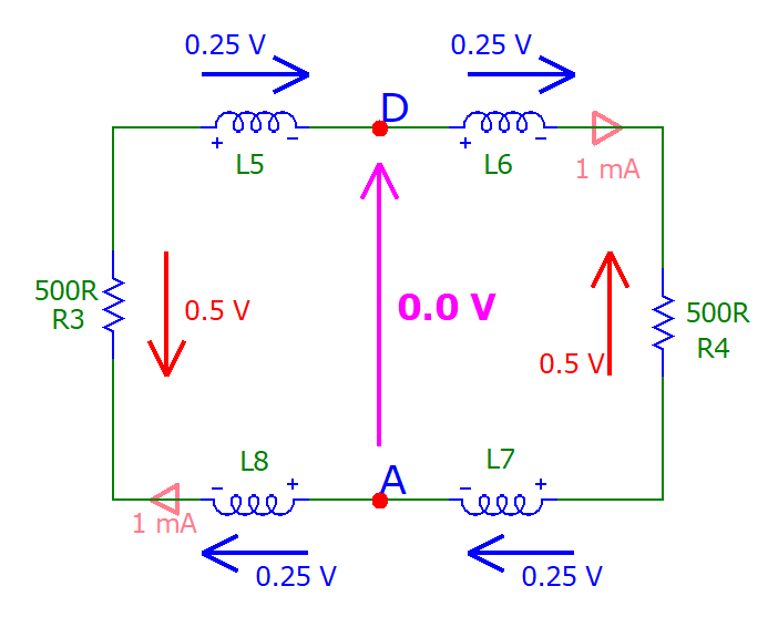
Summarizing: if we consider the current density j to be the same along the whole circuit (by taking the conductor and the resistor of the same diameter, only differing in material), we will see a very small electric field inside the highly conductive copper (hence no distribution of imaginary partial coils voltages inside the conductor), a big electric field inside the the small resistor (responsible for the 0.1V 'voltage' along the path going through it, the sign depends on the direction) and a much bigger electric field inside the bigger resistor (responsible for the 0.9V 'voltage' along the path going through it). The sum of all voltages along the loop (note that they have definite values because I am specifying a path) is not zero, but it's 1V, as predicted by Faraday's law.
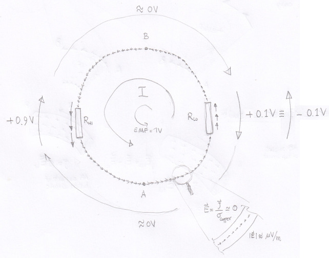
Note that there are no probes in the drawing above.
All voltages shown are single-valued because we are computing them specifying a path along the circuit (again, we have to specify the path because in non-conservative fields such integrals are path dependent).
The fact that we find two different values of the voltage between A and B (namely 0.9V and -0.1V) is an expected consequence of the fact that the whole circuit path is enclosing a variable magnetic field region, and thus ordinary circuit theory is not applicable.
So the answer to your question "what is the theoretical voltage between points A and B?" is "it depends, along which path do you want it computed?".

(I had to remove the rest, post too long)

