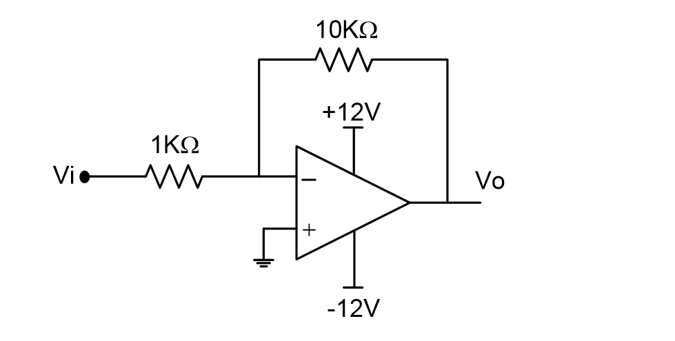
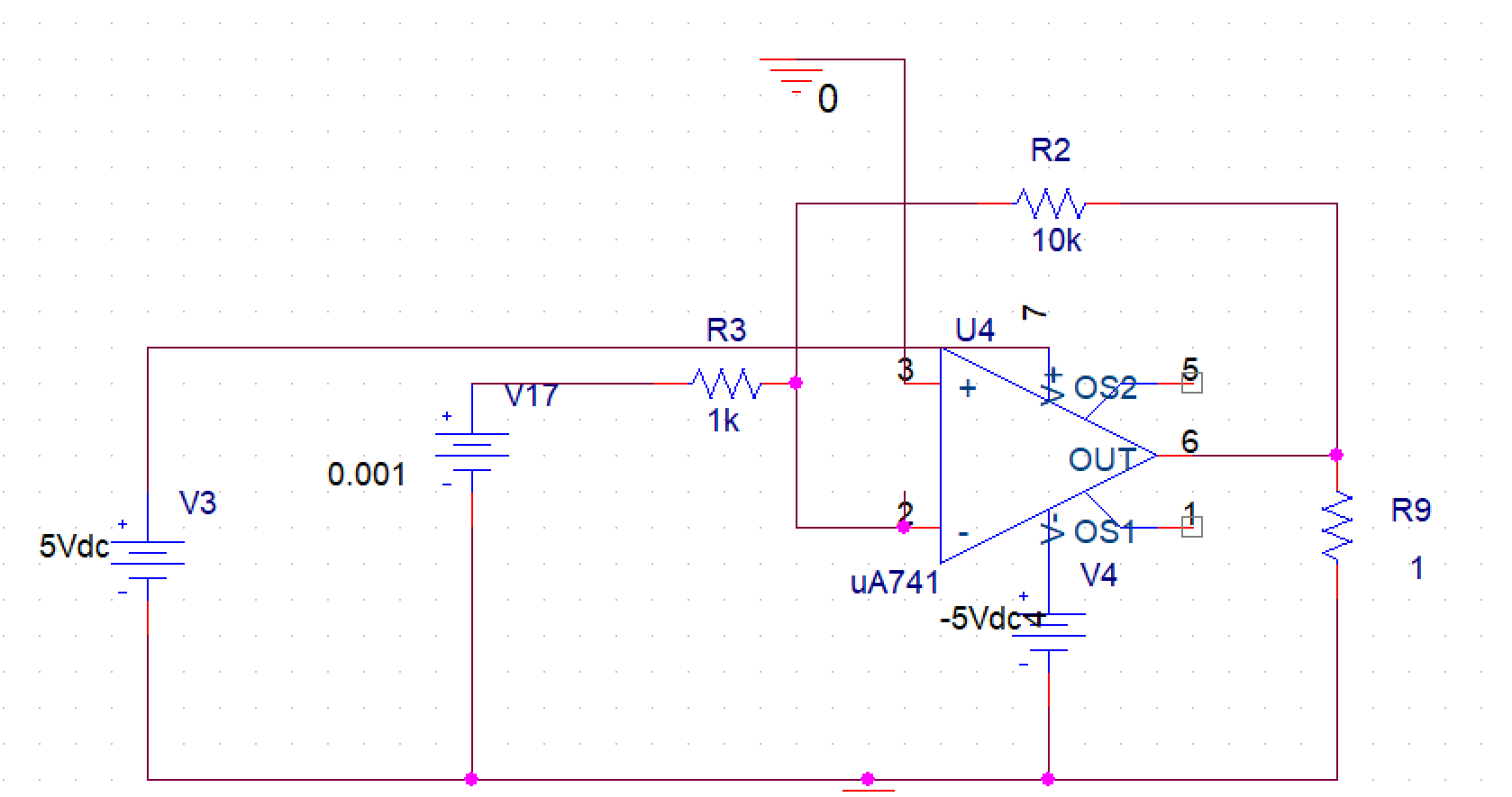
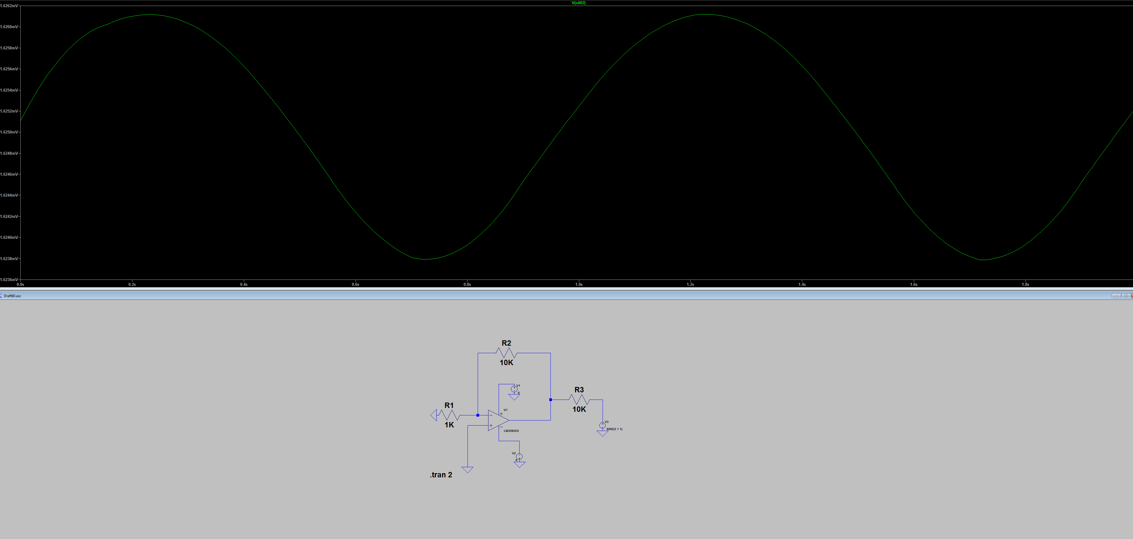
Apply a small voltage to the input like 0.1V, then measure the output without any load connected to the opamp, my simulator shows -987.88072 mV, then apply a 1Kohm load to the output and measure the voltage, my simulator shows -987.87663 mV. Now, use the voltage divider formula and solve for the opamp resistance as follows:
$$ OutputR = (\frac{Unloaded Voltage}{Loaded Voltage}-1)Load$$
So it should be
$$ OutputR = (\frac{-987.88072}{-987.87663}-1)1000$$
This gives an output resistance of 0.00414 Ohm
To check for consistency, the closed loop output resistance can be roughly calculated from the open loop output resistance as
$$ ClosedLoopR = \frac{OpenLoopR}{1+a \beta}$$
Where \$ a \$ is the open loop gain and \$ \beta\$ is the feedback factor
In the data sheet of the 741 the open loop output resistance is 75 Ohm and the open loop gain is 200,000 V/V. In the opamp circuit you presented, \$ \beta = 0.0909091\$ , so plugin everything into the formula gives a closed loop output resistance of 0.00412 Ohm, which is pretty close to the simulation result.


