0
\$\begingroup\$

As a continuation of the previously asked question and accepted answer Analog 0...10V signal splitting, I have a new question.

We implemented two analog buffers with LF353P and the rails are connected to 24V and 0V. We inserted the analog buffer between source and sink since the sink has capacitance on its input which affects our measurement. (Second analog buffer is redundant, but it can also be inserted between source and monitor)

The accepted answer works as intended with a slight problem. Signal coming out of the sink can reach 0V, and when the op-amp input signal is near 0V, the output from op-amp is at 22.#V which results in an error state in the sink.

My understanding is that this is because the input voltage is near the lower rail voltage of op-amp. If my reasoning is correct, the following circuit will be able to output 0V..10V (with both 0V and 10V being possible outputs): enter image description here
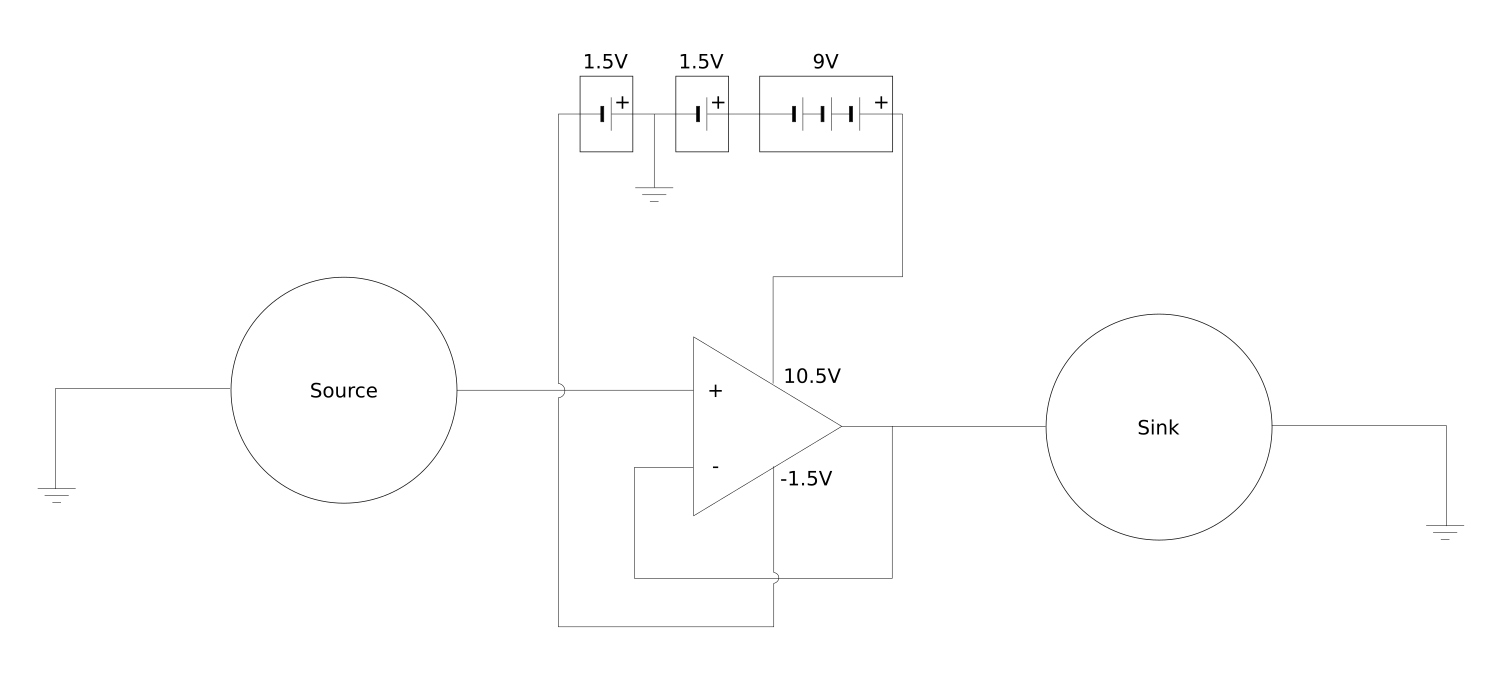
Those batteries should be able to drive op-amp for a long time since the current needed by op-amp and sink is measured in mA. Is my reasoning and approach to the solution correct?

\$\endgroup\$
2
  • \$\begingroup\$ You are exceeding the input common mode range and experiencing phase reversal. You could just use a rail-to-rail opamp. If you need true 0V output (and not just near 0V output) then you will need to provide a sligthly negative supply either way. \$\endgroup\$
    – DKNguyen
    Commented Jul 3, 2020 at 14:27
  • \$\begingroup\$ Most op-amps will need 2 or 3 volts headroom on the positive rail. \$\endgroup\$
    – Andy aka
    Commented Jul 3, 2020 at 14:29

2 Answers 2

1
\$\begingroup\$

That opamp (LF353P) only works to within 4 V of the supply rail, so won't work with the 1.5 V negative supply you show.

What you need is a rail-rail opamp such as TLV2771 -- see https://www.ti.com/lit/an/sloa039a/sloa039a.pdf

Depending on your high voltage, you may not need the middle 1.5 V cell. note that cells which are nominally 1.5 V will vary from 1.9 V (new) to 0.9 V at end of life. Thus your 9 V cell will also discharge to below 6 V.

\$\endgroup\$
1
  • \$\begingroup\$ Thank you for your answer. I'm lost in the naming convention of op-amps, and local shops have poor filtering options for their catalogs. Nevertheless, since our system has a 24V supply, I only planned for batteries to lower the voltage on the bottom rail. I spent some time perusing local shops, and I think that I found what I need: LM2904. If I'm correct, it is a rail-to-rail op-amp that can handle close to rail input/output, and it can run on 24V we have in system. It should be able to handle 0...10V signal that we need to buffer. \$\endgroup\$
    – stribor14
    Commented Jul 6, 2020 at 8:56
1
\$\begingroup\$

Some opamps use only ONE type of input diffpair; some opamps use TWO types of input diffpairs.

To handle rail-rail inputs, you need the second type of opamp.

\$\endgroup\$

Your Answer

By clicking “Post Your Answer”, you agree to our terms of service and acknowledge you have read our privacy policy.

Not the answer you're looking for? Browse other questions tagged or ask your own question.