A sequential circuit is often drawn like a feed back loop, with input(s) coming in on the left, a block of analog and/or digital logic generating the output(s) and feeding into the memory section with some of the outputs and then the output of the memory section feeding back into processing block. Mapping to a Finite State Machine drawing basically requires unrolling the loop. Since it is a sequential circuit the memory goes through discrete steps and thus doesn't have any capacitors or inductors, only digital storage devices like flip-flops or individual bits in a latch. Typically there is one bit of storage for each state although it is possible to use a small number of gates and treat them like a binary number to define which state the circuit is in, but this approach makes the logic block very complex as it must decode every state number as well as combine the inputs to generate the correct outputs and which state to transition to. But you can always replace the binary count with a separate memory cell for each state and greatly simplify the logic.

The first step is to look inside the memory block and look at the individual memory cells. The logic block will contain the logic to select which state to transition to next based on the current state and any inputs that affect which state to go to so I have drawn it here to show the logic output going to all memory cells and the state active signals all being combined to feed back into the logic block. For a finite state machine only one memory cell or state can be active at one time so the logic must generate exactly one trigger to activate the next state. Then each memory cell sends a signal feeding back into the logic that goes high when that cell is active. This is then combined with the current input by the logic block to generate the outputs and activate the next state by using the active line from the current state and any conditional logic used to test the inputs if there are multiple next states from the current state.

The next step is to look into the logic block and see which gates are active for each memory cell, which output(s) are controlled by each state and the logic, if any, controlling which state to go to next. It should be possible to separate the logic block into signals that only depend on the inputs which can be ignored for generating the FSM,and signals that depend in whole or in part on which memory cell is active. The memory cell dependent part can further be divided into circuitry for each memory cell. This step may involve making multiple copies of shared circuits but there should be a definitive circuit for each memory cell to define what effect, if any, that the inputs have on the transition to that state, what output(s) are generated by that state and how the inputs may affect those outputs, and also define which state or states it might transition to next with the inputs controlling which state will come next if more than one is possible. The example above is very simple, each state transitions to the next state except the last one which loops back on itself until a reset comes in and then state 1 is active again. On the outputs each state generates a single, unique output and only one, state 3, if affected by the input values.
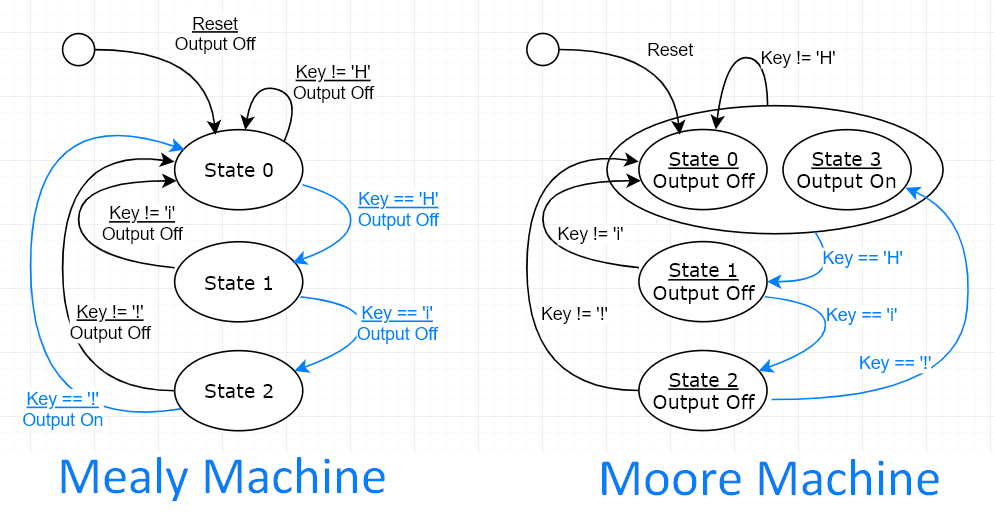
To further understand finite state machines, read the examples below where the sequence of states is not always as sequential and where the inputs have a greater effect on state transitions. It should also be possible to reverse this process and take a finite state machine and move all the states back into memory cells in the memory block and move all the logic back into one block. In cases like the one above, the transition from one state to the next is just a line going from the active signal of one memory cell to the set/activation of the next. If the sequential circuit was clock driven, an external clock would be one of the inputs and the logic block would control where it went. If the clock was asynchronous from the inputs then a local clock would be part of the logic block. It is possible to mix in some analog signals that may be controlled or conditioned by the various state outputs and may affect the logic block by using comparators, threshold detection, peak detection or other digital signals derived from analog inputs. For instance, an analog signal can either be very small but must be read with precision or can become quite large, so have it go through a digital AGC where the region of input from the last clock cycle determines whether the current signal is amplified or damped down.
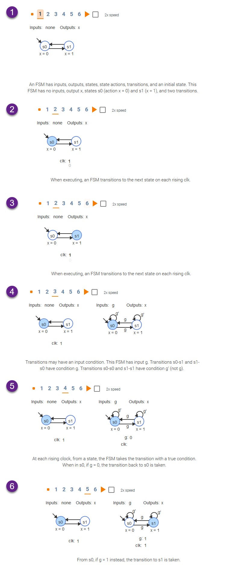
A Finite State Machine is a way of keeping track of some prior history while strictly limiting the detail of the 'memory' of the system. This contrasts with an infinite state machine like an analog audio filter. The filter is affected not just by the current voltage coming in but also by the charge on it's capacitor(s) and current through it's inductor(s), which are the integral of all the voltages that have come through before. It would take an infinite number of states to use state number to store that same information. The finite state machine requires that the history of how it got to that state be unimportant, only what being in that specific state implies and that it respond to the next input based solely on which state it currently is in.
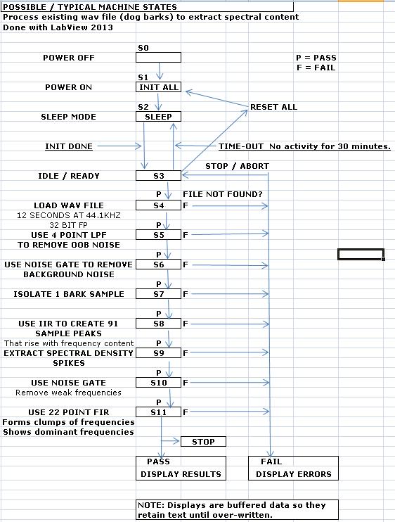
For example, a vending machine waiting for the next coin or a compiler tokenizer knowing how to respond to the next character depending on whether it is in the state of reading a number or a variable name. For a simple sequential circuit that would mean the circuit stage 1 performs its task and then turns processing over to stage 2 which runs till finished and hands off to stage three and so on. If there is no switching, jumping around some stages, holding at some stage until an external trigger allows it to continue, the finite state machine view is very simplistic with all the states leading only to the next stage like beads on a string. The finite state machine view of a sequential circuit is more useful if the timing or sequence of events is affected by outside values or triggers. To more fully understand a finite state machine, consider the examples below.
Consider a vending machine. For this example we will consider an older machine that takes nickels, dimes, and quarters only and dispenses any selection for 50 cents. The finite state machine would have a state for 0 cents, 5, 10, 15, 20, 25, 30, 35, 40, 45, 50, 55, 60, 65, 70, return 20, return 15, return 10, return 5, and vend. If you approach the machine when it is in the initial state of 0 cents then put in a nickel, it would go to 5 cents state, a dime would send it to 15 cents state, another dime to the 25 cents state. In each state the state itself keeps track of the money entered so far. The 25 cents state does not know if it was a nickle-dime-dime or a dime-nickle-dime or a nickle-nickle-nickle-dime or a quarter. The path that led to this state is unimportant, it only matters what credit has already been built up and if a new coin is inserted or the return change button pressed. All the states at or above 50 cents watch for a selection button to be pushed or the return change button and they lock out accepting any additional coins. But since it is possible to put in a quarter at the 45 cents state the machine has to allow for excess credit and to have states to control paying back the excess as well as actually controlling the vending process. Once the excess credit has been paid off and the vending process completes, it returns to the initial state of zero cents.
This example would be much more easily done today with a single microcontroller, but for the original vending machines which existed long before microcontrollers, it allowed simple relays to store the state and simple switch inputs to determine which state to go to next, and each state would have its own outs. In this case the outputs of each stage would drive different elements of LEDs, LCD, or other display device.
This limited memory approach lends itself to more modern problems as well. For instance a software compiler program would normally have a tokenizer to initially break up the input text into different syntax types, like variables, numbers, operators, or white space before passing the tokens on to the syntax layer. Below is a graphic of a simplified tokenizer. It looks very complicated but is actually very simple in operation. It is considerably simpler than trying to merge the text input routines with the syntax parts of the compiler which would require lots of if-then-else blocks and special cases and jumps from one section of code to another. Interestingly enough, the syntax portion of a compiler also works well as a finite state machine, but that is a question for a programming site.
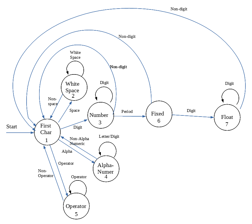
There are many different ways here to enter the initial state (1) so it can 'know' only that it is the beginning of a new syntax type whether that be the first character in the file or a number in the middle of an expression. It is because it responds the same to the next input regardless of what came before that a finite state machine works well here.
Assuming the state machine is currently in state 1, if the current character is a white space go to state 2 where it loops on more white space and then returns to the initial state 1. If it starts with a digit then it is a number, go to state 3 to process it as an integer, if the character is a letter than it goes to state 4 and is a variable name which can also contain digits as well as letters. This state machine is designed to require variable names to start with a letter and then be free to use letters and/or numbers. If the first character is a math or logic operator then it goes to state 5 and collects all the characters in that operator.
Notice that in state 1 a digit and a letter are treated differently. After the first character has been processed, the next character could be a digit which could be part of a number or part of a variable name. The state the machine is in when it receives that digit determines if it will be treated as a number or a name. This is the power of a finite state machine, that you don't have to scan back through some or all of the prior input to know whether the current character is part of a number or part of a name. If the integer collecting state 3 finds a period instead of a digit it goes on to state 6 to begin doing a fixed point or floating point number.
Notice here that the states do not have to go in sequential order. In fact when there are several possible destination states from the current state based on the current input, it is not possible to get them all in order, and the numbering scheme is quite arbitrary. If the period is not followed by another digit, it assumes that the number is the floating point equivalent of the integer and returns to the initial state. If more digits, then go to state 7 to build the rest of the fixed point number. For simplicity sake, true floating point numbers and other program elements were not included in this example.
A finite state machine will likely be a good choice if your job can be broken up into a modest number of independent tasks, each task handles the next input the same way regardless of what happened before (duplicating some tasks with slight changes to remove history dependence is ok) and the decision of which task to go to next is clearly defined for each task. If some tasks work more interactively with others, or large amounts of prior input information is needed, then finite state machines will probably not work well.

