0
\$\begingroup\$

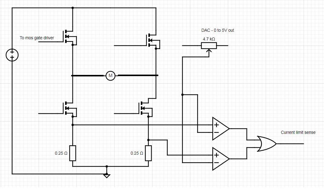
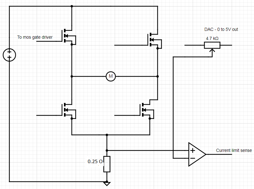
Are there any disadvantages in measuring H Bridge current only via 1 shunt resistor? Since it will be made by hand on a perf board the only disadvantage will be the possible longer wires that connect both drains of the lower N FET half bridges to the shunt resistor.

Mosfet driver will be ir2110/13 but that is a discussion for another post :) . I read application note from infineon and saw that there is a reverse current flow and ground going "below ground".

If I'm correct, current from forward biasing a diode when the bridge fets are HiZ will flow from ground to VCC and it will affect both configurations.

Output from the comparator/ OR gate goes into the classic Threshold reached -> shut off the bridge controller.

Yes, the sense resistors are huge but I don't care about the wasted power, resolution is of greater importance from DAC. And I forgot to put the ballast capacitor from VCC to Ground. Current of the bridge will max out at about 5 Amps.

comp only or powered

\$\endgroup\$
3
  • \$\begingroup\$ what are you trying to actually say when you say this: If I'm correct, current from forward biasing a diode when the bridge fets are HiZ will flow from ground to VCC and it will affect both configurations \$\endgroup\$
    – Andy aka
    Commented Jul 5, 2020 at 15:08
  • \$\begingroup\$ Bridge will be driven in fast decay mode so when the threshold current is reached all 4 fets go HiZ and body diodes conduct the current caused by collapsing magnetic field. \$\endgroup\$
    – Nik
    Commented Jul 5, 2020 at 15:15
  • \$\begingroup\$ @Andyaka Forgot to tell that it happens in dead time in slow current decay mode as well \$\endgroup\$
    – Nik
    Commented Jul 5, 2020 at 15:44

1 Answer 1

1
\$\begingroup\$

Sure you can use only one shunt, but you will have the information of PSU current, only. The configuration of two shunts possibly can be used to estimate the current through the load, although I don't have any information about the existence of this calculation and software implementation, I do think that's the reason of using two shunts.

EDIT: I do see now, you are tying to detect the current limit, only. I wrote my answer thinking you are using ADC to measure the current. So, it makes no difference to use a single shunt and single comparator for your needs. As for negative voltage on the shunt, you have to make sure that it will not exceed the comparator input voltage limits.

\$\endgroup\$
2
  • 1
    \$\begingroup\$ Well the idea pooped up after working with Bts7960. They are half bridges on single arduino Full bridge module and they each have the current sense out from an op amp (that does sensing on high side fet, had to do the thing with OR gates because 2 comparators were needed). Won't we get motor current on the shunt resistor and not Psu current? \$\endgroup\$
    – Nik
    Commented Jul 5, 2020 at 19:28
  • 1
    \$\begingroup\$ No, but if you use the comparator to detect the current limit, then these two currents are the same max PSU = max Motor current, I didn't see you were actually using a comparator as digital true/false output.. \$\endgroup\$ Commented Jul 5, 2020 at 19:50

Your Answer

By clicking “Post Your Answer”, you agree to our terms of service and acknowledge you have read our privacy policy.

Not the answer you're looking for? Browse other questions tagged or ask your own question.