3
\$\begingroup\$

I want to create a game, where players have to analyse a circuit in order to solve a puzzle. The players see 6 measuring points A to F and have a multimeter/continuity tester. They also have a few different schematics. They now have to find out which schematic is representing the circuit they have in front of them. The Circuits have random shorts or diodes between the measuring points and can look like this: 6 different Circuits with shorts and diodes
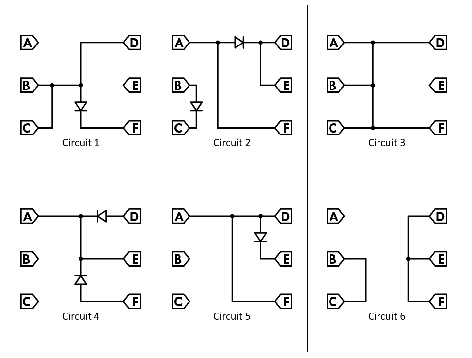
The thing now is, that I want to be able to generate random circuits with the help of a microcontroller. I'd like to have something like an Arduino simulating different circuits. They don't actually have to work, they just have to look like one of the circuits to a continuity tester.

If I could bruteforce my way through it, I could use 15 relays (one for each connection AB, AC, AD, AE, AF, BC, BD, ...) to switch on and off a short and 30 more relays for 15 diodes in one direction and 15 diodes in the other direction. But my PCB isn't big enough for that ;-)

Is there any other way to simulate shorts and diodes to a continuity tester using a microcontroller? I'd even be happy with something like "The microcontroller senses which points get measured and outputs something the multimeter/continuity tester can interpret". As I said, the circuits don't actually have to work.

Edit: I don't want to simulate the continuity tester. I want the players to learn how to use the "real thing".

\$\endgroup\$
7
  • 1
    \$\begingroup\$ Welcome. You create a look-up table with all the combinations you want to use. You create a random index to select one option per button-push. You output signals to relay drivers that make actual connections to test. That is the easy part... \$\endgroup\$
    – user105652
    Commented Jul 7, 2020 at 23:18
  • 1
    \$\begingroup\$ you do not have to simulate any part of the circuit ... all you have to do is to simulate the ohmmeter ... display controlled by the microcontroller ... the fake probes tell the microcontroller what it should display \$\endgroup\$
    – jsotola
    Commented Jul 8, 2020 at 0:54
  • \$\begingroup\$ I like @jsotola 's solution. Bury the display with the MCU module, make jumper cables with a series diode in them so that the MCU can detect (+) and (-) ends of the jumper, and then the MCU can display a result for that test. Or beep or something. Unless you really do want them to use an actual ohmmeter. \$\endgroup\$
    – jonk
    Commented Jul 8, 2020 at 0:58
  • \$\begingroup\$ arrange the 6 test points around a small LCD so that the circuit could be displayed ... the two test probes would be the two columns of a 2x6 keypad matrix ... the test points would be the rows in the keypad matrix ... touching a probe to the test point would be detected as a button press ... isolation diodes would prevent button press ghosting \$\endgroup\$
    – jsotola
    Commented Jul 8, 2020 at 1:10
  • 1
    \$\begingroup\$ I already got the version with the simulated ohmmeter, that one works great :-) Now I want the kids to use a real multimeter, so they can also use the same device on a real circuit. And that's where all the hassle comes in... \$\endgroup\$
    – Tetopia
    Commented Jul 8, 2020 at 8:47

3 Answers 3

3
\$\begingroup\$

Use analog switches driven from the MCU -- e.g. CD4066 - https://www.ti.com/lit/ds/symlink/cd4066b.pdf?ts=1594252952793&ref_url=https%253A%252F%252Fwww.google.com%252F

Each package has 4 switches, so you'll need a few packages. The switch resistance will be low enough for the continuity tester to think is a short.

\$\endgroup\$
2
  • 1
    \$\begingroup\$ Yes, and note that the switches are bi-drectional, like a relay -polarity of the tester/probes does not matter-, and they are low-ohmic. Here's a good intro: maximintegrated.com/en/design/technical-documents/app-notes/5/… \$\endgroup\$
    – P2000
    Commented Jul 9, 2020 at 18:18
  • 1
    \$\begingroup\$ Many of the datasheets state a "Typical On-State Resistance (Ron)". This can be as high as a few hundred Ohms or less than 1 ohm. I guess that is the resistance an ohm meter would measure when the switch is a "short"? 100Ω are surly to much for a continuity tester to think it's a short... So I guess I'd have to look out for a chip with an as low as possible Ron? \$\endgroup\$
    – Tetopia
    Commented Jul 12, 2020 at 17:45
1
\$\begingroup\$

Your previous answers show that changing "hardware" by software isn't trivial. So don't try to simulate the circuits. Build them for real on some small pcbs, select one randomly before each game, and plug it into the main pcb. Make the microcontroller detect which pcb is plugged in.

That's not a perfect solution, because new circuits always need some new pcbs. But at least those can be of any configuration you want without taking much space on the pcb. Other cons: The small pcbs can get lost. You might be able to guess which pcb is plugged in without actually measuring it.

\$\endgroup\$
1
  • \$\begingroup\$ I like this answer, and you can just solder it on strip boards and put a 2d barcode on or something that makes it sufficiently hard to read for the human and easy for a ... smartphone in this case. This way you can add all sorts of other circuits over time. And it's almost like a card-game! \$\endgroup\$ Commented Jul 14, 2020 at 19:30
-2
\$\begingroup\$

This is a question, it wants an answer. I will give one. And I challenge anyone else who can tell I am wrong to give the right answer and vote me down. Stop with the comments guys!

To have the full effect, the relays are your only option. That way you can use ohm-meter or just any battery with a light bulb, anything. I would go with that.

Theoretically, can I prove that this is the only right answer? Yes! As there is no other way to create the experience of a wire than a wire!

But is there really no solid state way? Yes there is, probably one close enough! How about you use a bunch of MOSFETs instead?

\$\endgroup\$
2
  • \$\begingroup\$ How about an optoisolator with an LED and an LDR, such that the LDR has very low resistance when the LED is on? You haven't proven anything because "the experience of a wire" is undefined in this case, and a relay by definition is not a wire. \$\endgroup\$ Commented Jul 12, 2020 at 18:40
  • \$\begingroup\$ @ElliotAlderson, so, black box thought experiment: you have a cube of 10 cm sides and two contacts on one face about 7 cm apart. You are supposed to tell me whether there's a wire in there or a relay in "on" state. How you're going to prove this? \$\endgroup\$ Commented Jul 14, 2020 at 19:34

Your Answer

By clicking “Post Your Answer”, you agree to our terms of service and acknowledge you have read our privacy policy.

Not the answer you're looking for? Browse other questions tagged or ask your own question.