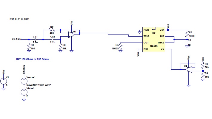
I'm working on getting an input from a cassette for a TRS-80 microcomputer (of 70's vintage). This is what I've worked up. It is a second order high pass active filter with rolloff frequency of 2kHz in a Sallen-Key topology with a unity passband gain, and I've used this as an input to a 555 timer with with appropriate threshold voltages.
I'm wondering if anyone has any suggestions, tips, pitfalls, tricks, things I've missed, notes, etc., that could help the design.
The output is just being dumped to a 1Meg resistor for simulation purposes - I'm assuming the thing reading this voltage will have a sufficiently high input impedance not to load the 555 timer's output.

I tried to pick reasonable values. I can upload the LTSpice schematic and waveforms if anyone's interested in following along!
Thanks all!
[Edit] R67 is a carryover from the original TRS80 schematic I was working from - it is to provide a path in case of DC offset. ;)
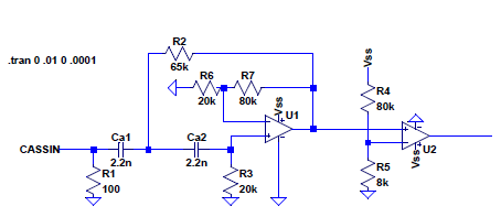
[Edit 2] Updated alternative schematic - using a second op amp open loop, changed design of filter stage to provide some gain. It should work if the second op-amp has a low enough internal capacitative load (something comparators don't have to contend with). I'm using an op-amp and not a comparator though because I am trying to get it done with one chip.

Any comments appreciated! Thanks!
[Edit 3] I have received some excellent tips from John Dunn, Consultant at Ambertec, P.E., P.C. If U1 and U2 are on the same chip, and U2 is being used as a comparator, there could be several problems.
Quoting John, "Depending on specific devices properties, an op-amp’s high and low output voltage saturation levels may not be close to the rail voltages. Also, transitions from one to the other may include bursts of oscillation. A true comparator won’t have these issues.
Another sticking point is that for some dual and quad op-amps, the op-amp specifications for linear service may not be met if one device in the set is railed. There can be undefined cross connections between the op-amp sections which can corrupt op-amp number one let’s say, if op-amp number three is being used as a comparator and is at either its high or low rail output limit."
John is an excellent guy who runs the Analog Developments group on Linkedin and was kind enough to provide some great insights. :)
