0
\$\begingroup\$

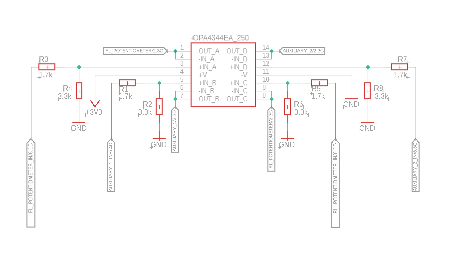
enter image description hereI have a question conserning some strange values I get when sampling a rotary potentiometer using an STM32F103CB MCU.

The circuit is as follows: Potentiometer(powered @+5V from a custom PCB) -> Voltage divider(0-5V to 0-3V3) -> OpAmp(OPA4344) -> MCU. On the MCU side the ADC is run in DMA and the result is sent to another device using CAN BUS. When observing the readings on the second board is where the strange behaviour is noticed. The potentiometer is placed inside a steering column so I know that there are equal degrees around the center, but if lets say at 0 degrees the pot reads 1750mV, the two equal distances read 10mV and 4995mV instead of 10mV and ~3500mV as someone might expect.

Any ideas what may cause this behaviour ?

Note: I checked with a multimeter the potentiometer and I observe the same readings I mentioned +/-60mV.

Note 2: In the second board, prior to displaying the data, I multiply by 4995/4095 to scale the readings from the 12-bit ADC values to mV.

Edit: The potentiometer is a B10K rotary potentiometer and its power and ground come from the PCB.

\$\endgroup\$
4
  • \$\begingroup\$ Welcome to EE.SE. A schematic is better than words. You can add one in using the CircuitLab button on the editor toolbar. Double-click a component to edit its properties. 'R' = rotate, 'H' = horizontal flip. 'V' = vertical flip. Note that when you use the CircuitLab button on the editor toolbar and "Save and Insert" on the editor an editable schematic is saved in your post. That makes it easy for us to copy and edit in our answers. You don't need a CircuitLab account, no screengrabs, no image uploads, no background grid. \$\endgroup\$
    – Transistor
    Commented Jul 12, 2020 at 11:16
  • 1
    \$\begingroup\$ Show all resistor values (including the potentiometer) in your schematic. \$\endgroup\$
    – Transistor
    Commented Jul 12, 2020 at 11:18
  • \$\begingroup\$ Exactly - where is the potentiometer and what voltages are connected to it. Be clear and don't put in stuff that doesn't add to your question. \$\endgroup\$
    – Andy aka
    Commented Jul 12, 2020 at 12:20
  • \$\begingroup\$ Potentiometer is placed inside a Formula Student project cars' steering column and is supplied +5V \$\endgroup\$ Commented Jul 12, 2020 at 13:45

1 Answer 1

0
\$\begingroup\$

The potentiometer is a B10K rotary potentiometer and its power and ground come from the PCB.
And you have it loaded by a 1.7k + 3.3k = 5 kΩ potential divider.

schematic

simulate this circuit – Schematic created using CircuitLab

Figure 1. The equivalent circuit.

enter image description here

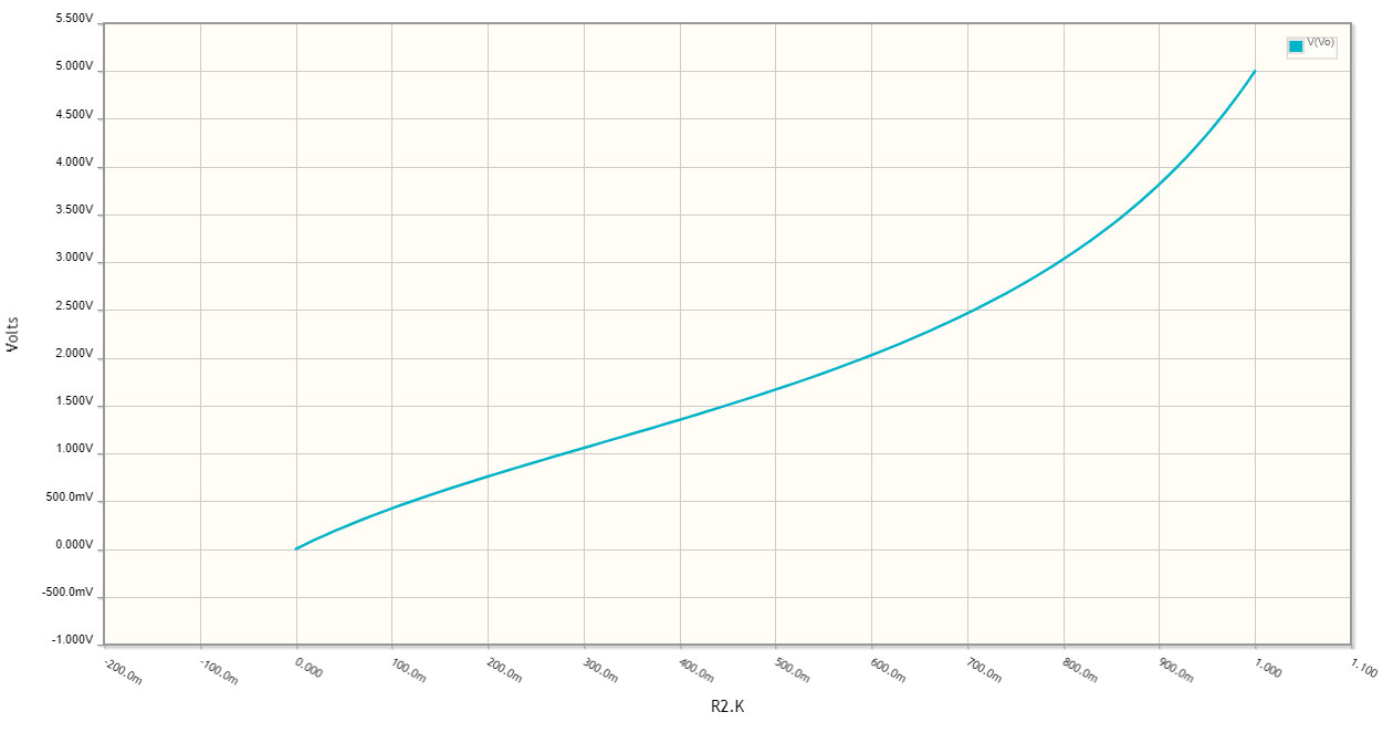
Figure 2. The output voltage as a function of potentiometer rotation.

Your potential divider is overloading the potentiometer. As you get closer to the top of the pot it begins to be able to control the load a bit better.

You should increase the potential divider resistance to be at least ten times the pot resistance.

\$\endgroup\$
5
  • \$\begingroup\$ And that explains the difference in the ranges left and right of the center of the pot ? \$\endgroup\$ Commented Jul 12, 2020 at 13:42
  • \$\begingroup\$ Yes. Look at the graph. At mid-position, (500 / 1000) the voltage out is 1.7 V on a 5 V supply so you're getting 1.7 / 5 = 34% instead of 50%. \$\endgroup\$
    – Transistor
    Commented Jul 12, 2020 at 15:12
  • \$\begingroup\$ Thank you very much. So you recommend replacing one of two resistors (1.7k or 3.3k) to a higher value one ? For example 100k ? \$\endgroup\$ Commented Jul 12, 2020 at 17:35
  • \$\begingroup\$ No, you would need to change both in the same ratio. Maybe 170k and 330k. They will hardly load the potentiometer at all. \$\endgroup\$
    – Transistor
    Commented Jul 12, 2020 at 18:00
  • \$\begingroup\$ Thank you for your help and time \$\endgroup\$ Commented Jul 12, 2020 at 19:46

Your Answer

By clicking “Post Your Answer”, you agree to our terms of service and acknowledge you have read our privacy policy.

Not the answer you're looking for? Browse other questions tagged or ask your own question.