1
\$\begingroup\$

I am currently studying The Art of Electronics, third edition, by Horowitz and Hill. Exercise 1.3 asks to prove the formulas for series and parallel resistors. I am given the following relevant information earlier in the chapter:

  1. The sum of the currents into a point in a circuit equals the sum of the currents out (conservation of charge). This is sometimes called Kirchhoff’s current law (KCL). Engineers like to refer to such a point as a node. It follows that, for a series circuit (a bunch of two-terminal things all connected end-to-end), the current is the same everywhere.
    enter image description here
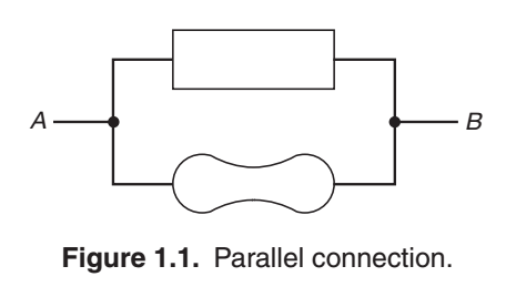
  2. Things hooked in parallel (Figure 1.1) have the same voltage across them. Restated, the sum of the “voltage drops” from A to B via one path through a circuit equals the sum by any other route, and is simply the voltage between A and B. Another way to say it is that the sum of the voltage drops around any closed circuit is zero. This is Kirchhoff’s voltage law (KVL).

I am trying to use this information (and ohm's law \$ V = IR \$, of course) to prove the parallel case \$R = \dfrac{R_1 R_2}{R_1 + R_2} \$. However, I do not understand how the provided information is sufficient to deduce this.

I am told that this is a good textbook, so perhaps it is just that I am new to electronics, and so I am not understanding something. Or, perhaps it is the case that the authors have failed to provide enough information to solve this problem without external knowledge. I would greatly appreciate it if people would please take the time to explain how it is possible to deduce this with the given information.

\$\endgroup\$
4
  • 1
    \$\begingroup\$ How are you new to electronics and have over 1k reputation on ESE? \$\endgroup\$ Commented Jul 18, 2020 at 5:57
  • \$\begingroup\$ @HelenaWells I have apparently asked some good questions during my studies (see my post history). \$\endgroup\$ Commented Jul 18, 2020 at 5:58
  • \$\begingroup\$ A “jackpot” question can get lots of rep: stackoverflow.com/q/3437059. And answers as well: stackoverflow.com/a/3437070. \$\endgroup\$
    – Ed V
    Commented Aug 5, 2020 at 18:07
  • \$\begingroup\$ @HelenaWells See my comment with links. \$\endgroup\$
    – Ed V
    Commented Aug 5, 2020 at 18:27

3 Answers 3

3
\$\begingroup\$

AoE is not a particularly theoretically inclined book, it's more of a practical guide with the minimum amount of mathematics that is required to do the analysis. Whether that is "good" or not depends on your goals in learning electronics.

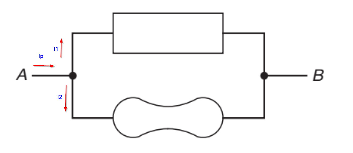
In any case, if we want to replace two resistors with one equivalent, we can calculate the equivalent resistor from the current that would flow. It's given that the voltage across each resistor is the same.

For R1 current is I1 = V/R1, With R2 current is I2 = V/R2, so the total current is:

I1 + I2 = V(1/R1+1/R2) and our "equivalent" resistor Rp = 1/(1/R1+1/R2) = R1R2/(R1+R2).

enter image description here

Adding the currents into the node: Ip - I1 - I2 = 0 (KCL) so Ip = I1 + I2

\$\endgroup\$
4
  • \$\begingroup\$ But what I don't understand is how one comes to this conclusion from the information in the textbook. \$\endgroup\$ Commented Jul 18, 2020 at 4:41
  • 1
    \$\begingroup\$ What part don't you understand? The equivalent resistor Rp replaces R1 and R2. The current Ip must be the sum of I1 + I2 by KCL. \$\endgroup\$ Commented Jul 18, 2020 at 4:44
  • \$\begingroup\$ Well, for one, it doesn't even mention "equivalent resistor", so I don't even know what this means. Furthermore, the only thing the author says about KCL is that "the sum of the currents into a point in a circuit equals the sum of the currents out (conservation of charge)", and it is not clear to me how I'm supposed to read this as \$ I = I_1 + I_2 \$. \$\endgroup\$ Commented Jul 18, 2020 at 4:53
  • \$\begingroup\$ See edit above. \$\endgroup\$ Commented Jul 18, 2020 at 5:39
4
\$\begingroup\$

It might be easier to understand how it works if you use the inverse of resistance - conductance.

In a parallel circuit each component has the same voltage across it, so the current flowing through it is independent of the others. Total current is the sum of the individual currents, so the total conductance is simply the sum of the individual conductances.

Take the example below:-

schematic

simulate this circuit – Schematic created using CircuitLab

R1 has a conductance of 1 / 1 Ω = 1 A/V, R2 is 1 / 2 Ω = 0.5 A/V, and R3 is 1 / 4Ω = 0.25 A/V. Add them all together to get a total conductance of 1.75 A/V, then invert the result to get the total resistance of 1 / 1.75 = 0.571Ω.

This gives the general formula for parallel resistances:-

\$\frac{1}{Rt} = \frac{1}{R1} + \frac{1}{R2} + ...\frac{1}{Rn}\$

In the special case of only two resistors in parallel you can rearrange the formula from

\$\frac{1}{Rt} = \frac{1}{R1} + \frac{1}{R2}\$

to

\$Rt = \frac{R_1 R_2}{R_1 + R_2}\$

\$\endgroup\$
3
  • \$\begingroup\$ So we have a total conductance of \$ 1.75 \ \text{A/V} \$, and a total resistance of \$ 1 / 1.75 = 0.571 \ \Omega \$; but if we use the total resistance formula directly, then we get \$ \dfrac{(1)(2)(4)}{1 + 2 + 4} = \dfrac{8}{7} \not= 0.571\$? \$\endgroup\$ Commented Jul 18, 2020 at 13:17
  • \$\begingroup\$ That formula only works with 2 resistors, not 3 or more. If you try to do it 'directly' with more resistors the formula gets more complex, making it less useful. With a calculator it's easier to do it the 'long' way. Just invert each resistance with the '1/x' button, hit 'MS' for the first one or 'M+' for the rest, then hit 'MR' and '1/x' to get the total resistance. \$\endgroup\$ Commented Jul 18, 2020 at 22:38
  • \$\begingroup\$ ok, thanks for the clarification. \$\endgroup\$ Commented Jul 19, 2020 at 2:43
2
\$\begingroup\$

schematic

simulate this circuit – Schematic created using CircuitLab

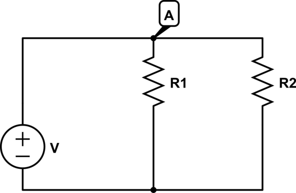
The total current in the circuit will be It = V/Rt

According to KCL It = I1+I2 where I1 is the current flowing through the R1 resistor and I2 is the current flowing through the R2 resistor.

If we substitute(Ohm's law):

V/Rt = V1/R1+V2/R2. But since the resistors are in parallel V1 = V2.

But since there isn't a resistor between the the voltage source and the resistors V = V1 = V2.

V/Rt = V1/R1+V2/R2 -> V/Rt = V/R1+V/R2 and if we divide by V we will get 1/Rt = 1/R1 + 1/R2.

\$\endgroup\$
3
  • \$\begingroup\$ Thanks for the answer. What do you mean that "there isn't a resistor between the the voltage source and the resistors"? That statement sounds a bit nonsensical, no? \$\endgroup\$ Commented Jul 18, 2020 at 6:16
  • \$\begingroup\$ There isnt any resistor between the positive terminal of the battery and A. \$\endgroup\$ Commented Jul 18, 2020 at 6:19
  • \$\begingroup\$ Oh, ok, I see what you mean \$\endgroup\$ Commented Jul 18, 2020 at 6:25

Your Answer

By clicking “Post Your Answer”, you agree to our terms of service and acknowledge you have read our privacy policy.

Not the answer you're looking for? Browse other questions tagged or ask your own question.