2
\$\begingroup\$

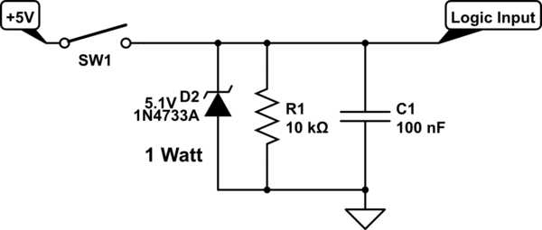
I am designing a logic circuit where the inputs are some switches and also some digital inputs are needed, below is an example of the circuit used to enhance the switches as digital inputs.

enter image description here

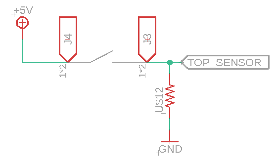
I am trying to add a pull down resistor for two digital lines which are the remaining inputs for the logic circuit.

Considering that when the digital input signal is not wired, the logic circuit needs to see 0V, How can I replicate this behavior for a digital input signal?

I thought of a pull down resistor, but as I don't know the output impedance of the circuit driving the input of the logic gate, how can I come up with a good value for the pulldown resistor?

\$\endgroup\$
4
  • \$\begingroup\$ So, in the final circuit, the TOP SENSOR input will be connected to two wires, one coming from the manual switch and one coming from a digital circuit ? \$\endgroup\$
    – AJN
    Commented Jul 20, 2020 at 6:15
  • \$\begingroup\$ I might have not explained well, TOP SENSOR represents 4 of the 6 inputs for the Logic circuit, I am trying to add a pull down resistor for two digital lines which are the remaining inputs for the logic circuit. \$\endgroup\$ Commented Jul 20, 2020 at 6:23
  • \$\begingroup\$ You may find the following pull-up resistor tutorial useful: "Pull-up Resistors - Electronics Tutorials": electronics-tutorials.ws/logic/pull-up-resistor.html. Cheers. \$\endgroup\$
    – tlfong01
    Commented Jul 20, 2020 at 6:23
  • \$\begingroup\$ As Audioguru commented the answer is orders of magnitude different depending on presence and value of pull-up resistors in "the remaining circuit". \$\endgroup\$
    – greybeard
    Commented Mar 8, 2023 at 7:12

2 Answers 2

1
\$\begingroup\$

The input impedance of a CMOS logic gate can be over 100 Mohms, but you do not want a high resistive value unless this is battery powered. Normally to keep sensitivity to noise down the resistor would be from 10 K ohm to 100 K ohm.

A 10 K pull-down means when the switch is closed the resistor is draining 500 uA of current, and the 100 K would drain 50 uA of current. 1 megohm would draw just 5 uA of current but the high impedance would make the input sensitive to local noise and at elevated temperatures gate leakage could be an issue.

If you have a choice in the matter the 10 K is the best option, but if this is battery powered and every uA counts then use 100 K pull-downs. To cut way down on noise sensitivity you can parallel a 10 nF or 100 nF capacitor with the pull-down resistor.

The following is a basic digital input filter / clamp with pull-down resistor. Theses can be tiny SMD parts that take up little space.

schematic

simulate this circuit – Schematic created using CircuitLab

\$\endgroup\$
3
  • \$\begingroup\$ While the input impedance of a logic gate is very high, the input impedance of a CMOS chip is much lower because of the ESD protection circuits. I think a common specification for CMOS chips is 1uA of leakage current, so using a 1megohm resistor would cause a voltage as high as 1V on the input....not good. \$\endgroup\$ Commented Jul 20, 2020 at 14:03
  • \$\begingroup\$ @ElliotAlderson That is why I recommended 10 K to start with. Normally it takes elevated temperatures to bring out such high leakage. I have measured gate voltage with a 10 Mohm DVM Fluke 87-5 and it was only millivolts of leakage. \$\endgroup\$
    – user105652
    Commented Jul 20, 2020 at 18:33
  • 1
    \$\begingroup\$ The logic family was not told. It might be antique TTL that needs an input pull down resistor of less than 500 ohms. 250 ohms works well. \$\endgroup\$
    – Audioguru
    Commented Jul 21, 2020 at 2:45
0
\$\begingroup\$

Almost any value will work, but 10K-1M are typical. If running on battery you'd want to make it high to limit current draw when switch closed. But make it too high and nearby high speed traces may capacitively couple into it, or input leakage will develop too much voltage across it.

One thing to look out for: if TOP_SENSOR goes directly to a processor i/o pin, it's probable that pin has a programmable pullup/pulldown resistor option inside. Make sure it's not set to a pullup, as it will fight your pulldown. If you can configure it as a pulldown then you don't need the external resistor at all.

\$\endgroup\$

Your Answer

By clicking “Post Your Answer”, you agree to our terms of service and acknowledge you have read our privacy policy.

Not the answer you're looking for? Browse other questions tagged or ask your own question.