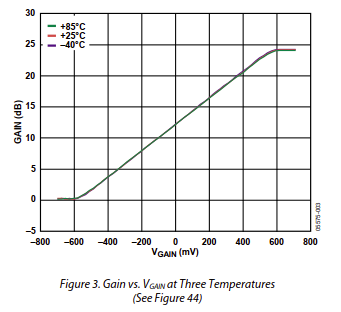
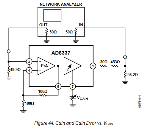
I seem to be getting something pretty close to the datasheet:

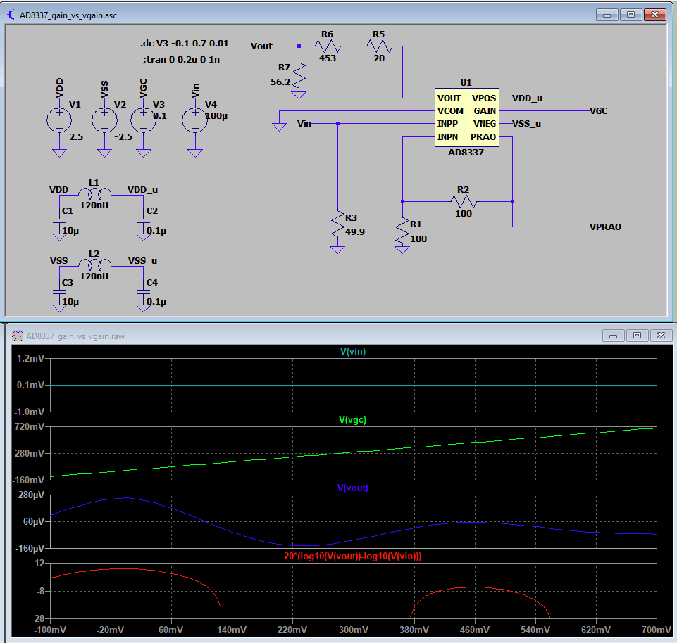
but I had to probe immediately after the pin for the output (V(x)), otherwise there would have been some 18 dB missing (V(o)). The input is also a more meaningful 0.1 V (accounted for in the plot window as *10). Another thing that's corrected from your schematic is the proper use of an input resistance: you placed it across the voltage source, which is useless, instead of in series. I also didn't use LC filtering since the only noise here is the double residuals. The symbol is the generic [Misc]/DIP8, for the lack of one, but the pinout is the same. Also, in your waveform window, did you use log minus log? The correct way is 20 * log10( V(out) / V(in) ).


