0
\$\begingroup\$

ATTiny is generating PWM based tones with 32kHz sampling rate. Then I've created R-2R DAC and then trying to amplify it for the speaker.

I need to make low pass RC filter, to cut PWM hiss during playback and some white noise during silence. I have tried to make use of bypass pin but no difference.
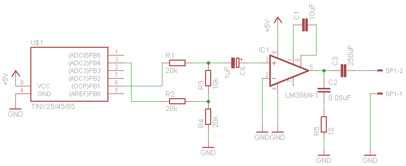
diagram

So where should I place RC filter and what values in order to filter out PWM hiss and noise during silence?

Update(without scope, I've tried to describe the problem as much as I can):

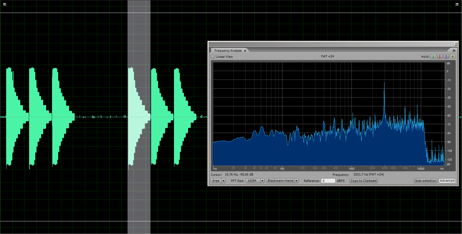
This is captured on DAC output using sound card, to describe the signal.

Enlargeenter image description here

actual .wav file of the capture download: https://www.dropbox.com/s/pwakovmu9h695ji/beep1.wav

Since my sound card is not able to capture the white noise I hear from speaker, I've tried to record voice using my phone.

http://www.youtube.com/watch?v=MM2n1Q92hIo&feature=youtu.be

Sec 22 I turn off speaker pin. Sec 31 turn on again.

\$\endgroup\$
2
  • \$\begingroup\$ Are you PWMing at 32khz, or a higher frequency? \$\endgroup\$
    – pjc50
    Commented Dec 15, 2012 at 13:14
  • \$\begingroup\$ At 32kHz, similar to this project elm-chan.org/works/mxb/report.html \$\endgroup\$
    – Pablo
    Commented Dec 15, 2012 at 15:25

3 Answers 3

1
\$\begingroup\$

You can use the DAC itself as the R part of the filter, and put a C from the DAC output to ground. The DAC appears as a 10k resistor.

What value of C? That depends on the highest frequency you want to generate. I'm going to assume 3dB attenuation at 4kHz is OK, so R = 1/(2*pi*f*C) where R=10000, f=4000, solve for C.

I get 4 nF.

(Incidentally the electrolytic cap C6 is shown wrong way round, + is connected to approx 0V)

I believe you also need to attenuate the input to the amp, it must be clipping at the moment. That attenuation will also reduce the hiss, and allow a second stage of filtering. For example, 20K in series with C6, 10K and 4nf in parallel from pin 3 to ground. Add this if the first filter isn't enough.

\$\endgroup\$
8
  • \$\begingroup\$ I will update my post with the useful signal characteristics shortly. thanks \$\endgroup\$
    – Pablo
    Commented Dec 15, 2012 at 12:02
  • \$\begingroup\$ The issue with doing this is that is causes different bits in the DAC to have different time-constants. \$\endgroup\$ Commented Dec 15, 2012 at 12:05
  • \$\begingroup\$ with a 2-bit DAC, is that going to be a significant problem? \$\endgroup\$
    – user16324
    Commented Dec 15, 2012 at 12:14
  • 1
    \$\begingroup\$ @FakeName: No, that's incorrect. The DAC has a fixed output impedance of 10K. It doesn't vary from bit to bit. If you don't believe me, work out the Thevenin equivalent circuit for yourself. \$\endgroup\$
    – Dave Tweed
    Commented Dec 15, 2012 at 12:22
  • \$\begingroup\$ @DaveTweed - Derp, You're correct. I was thinking that the pins driving the DAC were either high or high-impedance for some bizarre reason (or I wasn't thinking at all). \$\endgroup\$ Commented Dec 15, 2012 at 13:22
1
\$\begingroup\$

You have not addressed the fact that you have far, far too much gain.

The LM386 has a fixed minimum gain of 20.

Your R-2R DAC has a output range of 0V-3.75V

With a gain of 20, your theoretical output voltage range would be 0-75V

Basically, you have a 2-bit DAC, with only one-bit of effective resolution.

You need to use a better amplifier. An more common op-amp, such as a TL081 or similar, would work a lot better. Just use it as a unity-gain buffer.

\$\endgroup\$
4
  • \$\begingroup\$ Not if he's driving an 8 ohm speaker! The 386 is fine; it's easy to attenuate the input once the other problems are under control. \$\endgroup\$
    – user16324
    Commented Dec 15, 2012 at 12:44
  • \$\begingroup\$ @BrianDrummond - He'd have to attenuate before the amp, then. As drawn, it will rail the output. As such, you can't get meaningful results by measuring the output. I don't see how he can get his problems under control , as they're all tied directly to the LM386, which you can't test when railed. \$\endgroup\$ Commented Dec 15, 2012 at 13:19
  • \$\begingroup\$ @fake_name : of course! Attenuate the input = before the amp. \$\endgroup\$
    – user16324
    Commented Dec 15, 2012 at 13:31
  • \$\begingroup\$ @Fake Name: if possible I would like to use 1 IC, either LM386 or TL081. As far as I understood, with TL081 I have to use 2 ICs, buffer and final amp. correct? \$\endgroup\$
    – Pablo
    Commented Dec 15, 2012 at 23:52
0
\$\begingroup\$

I would think that placing the filter (assuming you're talking about a simple 1-stage RC filter) between your coupling cap (C6) and the opamp input would be best to get rid of the PWM hiss. The values will depend on the filter characteristics you want (i.e. how much you want to attenuate the 32kHz).

\$\endgroup\$

Your Answer

By clicking “Post Your Answer”, you agree to our terms of service and acknowledge you have read our privacy policy.

Not the answer you're looking for? Browse other questions tagged or ask your own question.