29
\$\begingroup\$

I am designing a circuit that needs to output 5VDC @ 1A. I'm trying to use a wall transformer to step the voltage down to 12VAC. The next step is the diode bridge and ripple capacitor.

The ripple voltage equation is:

$$V_{ripple} = \frac{I}{2fC}$$

I = load current (1A)
f = AC frequency (60Hz)
C = Filter Capacitor (? uF)

If I choose a C of 1000 uF, the ripple voltage is 8.3 V! Do I really need to put more capacitance to lower the ripple voltage? Is there another method of converting AC to DC?

\$\endgroup\$
3
  • 6
    \$\begingroup\$ You could save yourself the diode bridge and rectification if you used a DC wall transformer instead of an AC wall transformer. You would still need a voltage regulator to get a stable 5V though, almost all wall transformers are NOT voltage regulated, and a '5V' wall transformer will more likely give you somewhere between 5V and 9V. \$\endgroup\$
    – davr
    Commented Nov 17, 2009 at 19:10
  • 3
    \$\begingroup\$ I use 2000\$\mu\$F/A as a rule-of-thumb (sometimes more, depends on the application) \$\endgroup\$
    – stevenvh
    Commented Jun 28, 2011 at 14:27
  • \$\begingroup\$ Why not just buy one? Why reinvent the wheel? \$\endgroup\$ Commented Mar 12, 2016 at 14:05

6 Answers 6

41
\$\begingroup\$

1000 µF at this voltage isn't terribly big. Are you limited by size or something?

To completely get rid of the ripple and produce 5 V, you need to add a voltage regulator after the capacitor.

12 VRMS = 17 VPeak, which, minus the two diode drops, is the peak DC voltage you'll see at the output of the rectifiers: 17 - 1.1 - 1.1 = 14.8 V. So there's no threat of exceeding the input limits of the regulator (35 V input).

If the ripple is 8.3 V, then the DC voltage will be varying from 6.5 V to 15 V. This is just barely high enough to feed into the regulator without dropping out of regulation, since the 7805 has about 1.5 V dropout at 1 A (depending on temperature). So yes, you should use a slightly higher capacitor (or multiple capacitors in parallel, if space is an issue).
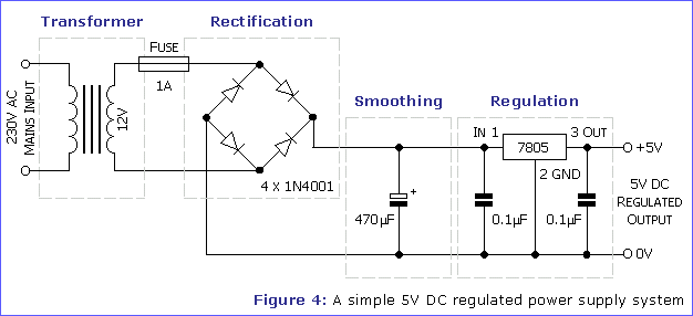
enter image description here (Source: Alan Marshall)

Here's a guide to each stage of the power supply circuit.

Also:

Real life power line voltages vary from one outlet to the next, and the frequency varies by country. You need to calculate the low line/high load condition to make sure it doesn't drop below regulation, as well as the high line/low load condition to make sure it doesn't exceed the regulator's input voltage limit. These are the generally recommended values:

  • JP: 85 VAC to 110 VAC (+10%, -15%), 50 and 60 Hz
  • US: 105 VAC to 132 VAC (+10%), 60 Hz
  • EU: 215 VAC to 264 VAC (+10%), 50 Hz
\$\endgroup\$
8
  • 1
    \$\begingroup\$ The peak voltage seen at the output of the rectifier will be 2 diode drops (2.2 V total) less than the input peak voltage. \$\endgroup\$ Commented Nov 17, 2009 at 19:43
  • 8
    \$\begingroup\$ Endolith has an exceptional approach. I would like to note one thing, USE A HEAT SINK. If you are going to put 1 amp through a linear regulator, use a heat sink, it is a lot more power to dissipate than people realize. \$\endgroup\$
    – Kortuk
    Commented Nov 17, 2009 at 20:15
  • 3
    \$\begingroup\$ Quick point: 2 diode drops isn't necessarily 2.2v. The voltage drop of a PN junction is very much dependant on it's construction and the type of semiconductors involved. They will even vary among devices of the same type. Mind, as well, that the 7805 is fine as long as it's got more than two or three volts of head room to regulate in. The higher the input, however, the more power it has to dissipate. Switching regulators, while somewhat more complex, are enormously more efficient. \$\endgroup\$ Commented Nov 30, 2009 at 15:13
  • 1
    \$\begingroup\$ 1N4004 datasheet lists 1.1 V drop for 1 A of current and KBP005 bridge rectifier lists 1.0 V for 1.0 A, so it's a typical value. \$\endgroup\$
    – endolith
    Commented Nov 30, 2009 at 22:25
  • 2
    \$\begingroup\$ you sometimes also see a diode across the 7805, anode to the input, so as to clamp the output from going (much) higher than the input - how necessary/unnecessary would that be? \$\endgroup\$
    – JustJeff
    Commented May 19, 2010 at 22:46
19
\$\begingroup\$

The thing is that these days switching power supply adapters are such a commodity item that unless you really want to get into the design for learning purposes, just buy one. Digikey has a few that are under $10 in single quantities (here's one from CUI) and will give you regulated DC output, with high efficiency, complete with all the safety and EMI/RFI certifications.

\$\endgroup\$
1
  • \$\begingroup\$ I use CUI all the time! There are also PCB mount versions, if you have AC at your board already. \$\endgroup\$ Commented Jul 28, 2011 at 1:13
8
\$\begingroup\$

If your capacitor is big enough to get the ripple down, your Vdc will be around 15V as shown by Endolith. Let's consider it drops a little under load, and use 12V as an example. If the output needs to be 5V, the regulator should take 7V at 1A, which means it should be able to continuously dissipate 7W of power. Depending on your application, this may or may not be an issue.

Why don't you just use a switching power adapter? These days there are a lot of routers, network switches/hubs, harddrive enclosures, etc. which use 5V. Their power supplies are usually not bigger then a regular wall transformer, are more efficient and the output voltage is well regulated.

\$\endgroup\$
7
\$\begingroup\$

Another method is to add a choke (inductor) in series before the final filter cap. Something like 100 uH would do a world of good. A coil resists changes in current, just like a cap resists changes in voltage. Put the two together and you get a much more effective filter.

You have an error in your Vripple equation. As you are using a full wave bridge, your freq is not 60 hz, but 120.

\$\endgroup\$
5
  • \$\begingroup\$ I had a "2*" to compensate for the full bridge. \$\endgroup\$ Commented Nov 19, 2009 at 16:20
  • \$\begingroup\$ Do you have a web site that describes the choke method? \$\endgroup\$ Commented Nov 19, 2009 at 16:22
  • \$\begingroup\$ Look up things like high pass filters, they take advantage of the fact that inductive reactance increases with frequency, while capacitive reactance decreases. \$\endgroup\$ Commented Nov 30, 2009 at 15:16
  • \$\begingroup\$ A inductor does resist changes in current, but keep in mind that your circuit may want to change current rapidly. When you change the current needed for the circuit the inductor will have to dump the current somewhere. \$\endgroup\$
    – Kellenjb
    Commented May 20, 2010 at 1:39
  • 1
    \$\begingroup\$ The inductor should be placed before the diode bridge, not after the regulator. If large enough it can increase the PTX conduction angle to 360 degrees and reduce its output current peaks and valleys to flat. But you lose some voltage. See Radio Designer's Handbook pp. 1162, 1182&ff. \$\endgroup\$
    – user207421
    Commented Mar 12, 2015 at 21:38
4
\$\begingroup\$

Your Vripple equation is only an approximation, and only good for small amounts of ripple.

Find a better equation, or solve it graphically, and you will see your ripple isn't as much as you think.

\$\endgroup\$
2
  • \$\begingroup\$ Good point about the limitations of that equation! \$\endgroup\$ Commented Nov 19, 2009 at 16:23
  • 1
    \$\begingroup\$ Here is a somewhat better equation for cases where Vripple is large. This is less pessimistic than Vripple = I/(2fC), but it is still pessimistic for values of Vripple < 1/2 * Vpeak. Instead of assuming there is no rising sine wave at t=1/2*f, approximate the rectifier output with triangles instead of sine wave (to make the math easier). Solving the two equations to see when the capacitor's falling voltage intercepts the rising triangular wave, to get: Vt = Vp * (4fCVp/I -1) / (4fCVp/I +1) f=60, C=1000, Vp=14.8, I=1 Vt = 8.3 volts Which is nicely above 7805 dropout voltage of 5v + 1.5v . \$\endgroup\$ Commented Nov 20, 2009 at 8:38
3
\$\begingroup\$

If you do not want to go the switching route a 5 or 6 volt transformer with lots of cap. and a low drop out regulator would help effiency a lot. You have to do some calculations to get the values and see if they are reasonable.

\$\endgroup\$

Not the answer you're looking for? Browse other questions tagged or ask your own question.