3
\$\begingroup\$

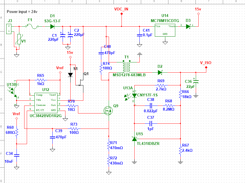
I am currently trying to find a solution to switching the supply voltage for U12 (PN: UC3842BVD1R2G) in the included schematic. What is special here is that U12 will draw 22mA no matter the input voltage I tested at, I did a sweep from 13v to 30v and it always only pulled 23mA. The issue here, is that even though it can be supplied with 30v, running it off the usual 24v causes the chip to run at 170 F, which in my case is a problem, and is near the high end of the recommended temps. Running the chip at 15v however, causes it to run at about 120 F, much better. The other issue with just trying to connect a 15v regulator right away is that the chip needs over 16v to start the circuit, then can be brought back down to 12-15v and run off of that.

I am attempting to start u12 on the input voltage, then when the regulator starts up, to use that to turn off Q1, changing the input from the 24v line to the 15v line. However, I don't think that would work, and was wondering if there is a normally closed held open kind of device that could do something like this? I also don't have a lot of space on this board for some type of relay either, or that would have been first choice.

Any help appreciated.

enter image description here

\$\endgroup\$
9
  • 1
    \$\begingroup\$ You can use a thermistor (Negative temp coefficient) and a normal resistor and create a voltage divider that divides rectifier 24V. After certain time, the resistance of the thermistor decreases and its voltage drop decreases. So you start off with 17V then drop below 15V. \$\endgroup\$
    – varun
    Commented Aug 13, 2020 at 17:02
  • 1
    \$\begingroup\$ Can you use the larger package with the split Vcc and Vc? then you could run them at seperate voltages and use a circuit to give the 5V regulator 6V and dissipate the power outside of the part, then run Vc at whatever you want. \$\endgroup\$
    – Voltage Spike
    Commented Aug 13, 2020 at 17:09
  • 1
    \$\begingroup\$ Why not just use UC3843B, with lower UVLO threshold? \$\endgroup\$
    – The Photon
    Commented Aug 13, 2020 at 17:11
  • \$\begingroup\$ @ThePhoton currently, this is a replacement for the 3843B due to availability \$\endgroup\$
    – James S
    Commented Aug 13, 2020 at 17:41
  • 2
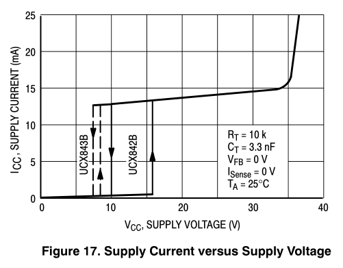
    \$\begingroup\$ Look at Fig 17 in the datasheet. You can use a weak pull-up to Vin diode-or'd to your 15V supply. Make sure to add a bypass caps near the Vcc pin. \$\endgroup\$
    – sstobbe
    Commented Aug 13, 2020 at 17:55

1 Answer 1

1
\$\begingroup\$

I am attempting to start u12 on the input voltage, then when the regulator starts up, to use that to turn off Q1, changing the input from the 24v line to the 15v line. However, I don't think that would work

You are correct, that won't work. The FET will be turned off when the 15v rail is low and turned on when it is up - the opposite of what you want. Also since it is a junction FET a significant amount of current will flow from the Gate to the Source.

But you don't need to switch off the 24 V supply. During startup the UC3842B draws less than 1 mA, so a simple resistor is all you need to get it going (eg. 6.8 kΩ would drop the supply voltage to 17.2 V at 1 mA). The higher current draw when running will automatically pull the voltage down until the 15 V supply takes over through diode S1. A small portion of the operating current will still be supplied by the resistor (~1.4 mA with 6.8 kΩ), but this doesn't heat up the IC any more than running it directly from the 15 V rail.

enter image description here

The only other change needed is an input filter capacitor (eg. 47 uF) from Vcc to ground. This stabilizes Vcc and slows its rise time to (hopefully) give the 15 V supply enough time to get up before the UC3842 starts up.

\$\endgroup\$

Your Answer

By clicking “Post Your Answer”, you agree to our terms of service and acknowledge you have read our privacy policy.

Not the answer you're looking for? Browse other questions tagged or ask your own question.