1
\$\begingroup\$

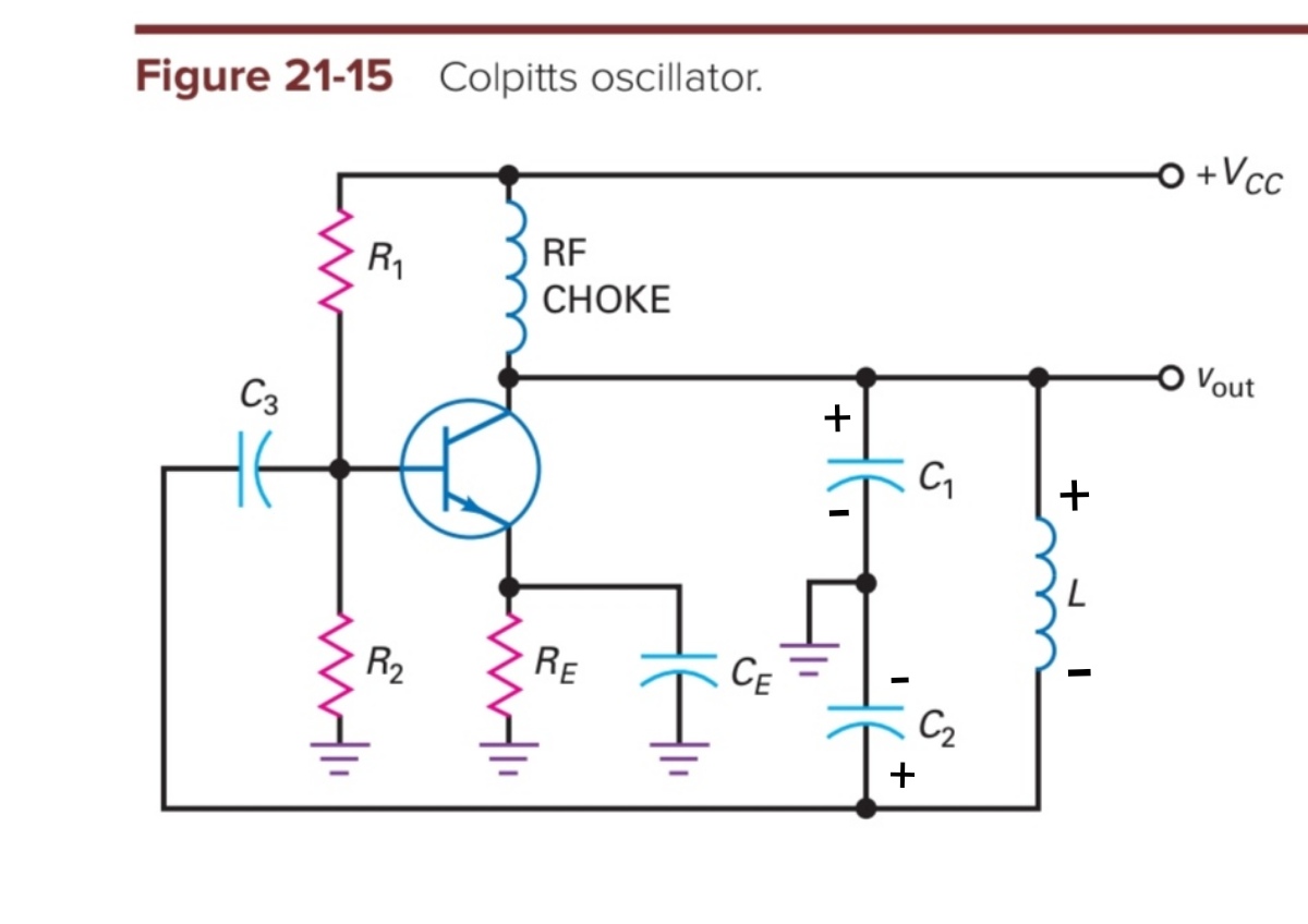
This is a Colpitts oscillator in a common-emitter configuration:

enter image description here

For oscillation to occur, there must be a positive feedback. But I'm confused how can this oscillator provide a 360° degree turn for the input signal.

At time t=0, DC current passes through RF choke and goes to C1 branch and L-C2 branch which both goes straight to ground. I added the polarity for C1, C2, and L above. From what I can see, the polarity for C2 forward biases more the base-emitter diode thus the collector current sinks and collector voltage decreases. This seems to contradict the preceded polarity (which is positive). With this, I think voltage will not build-up and oscillate.

What am I missing?

\$\endgroup\$
1
  • \$\begingroup\$ When collector "flies up", the bottom of C2 "flies down" (not up). The top of C1 is out-of-phase with the bottom of C2. \$\endgroup\$
    – glen_geek
    Commented Aug 14, 2020 at 14:35

3 Answers 3

2
\$\begingroup\$

The feedback path is a third-order lowpass (ladder topology): ro-C1, L-C2.

This assumes that the parallel connection ro||RF is app. identical to ro (Transistor output resistor ro). Furthermore, the impedance of the coupling capacitor C3 is neglected.

The output of this lowpass (node between L and C2) is fed back to the amplifier which provides 180deg phase shift.

There will be one single frequency fo where the feedback circuit (lowpass) also provides 180 deg phase shift (3rd order with max. -270 deg phase shift). This allows a 360 deg phase shift at the oscillator frequency fo.

General answer to your question:

The oscillation condition (Barkhausen) is formulated in the frequency domain (gain and phase of the frequency-dependent loop gain). This condition requires a certain phase shift (360 deg) for one single frequency only. This implies that the ability of a circuit to oscillate must be analyzed in the frequency domain.

Therefore, your attempt to make an analysis in the time domain cannot be succesful.

\$\endgroup\$
2
\$\begingroup\$

It has a parallel resonant circuit L and C1 & C2 in series. If the midpoint of a resonant circuit is grounded (in this case it happens between C1 and C2, it can as well be the center of the coil) the ends of the resonant circuit have opposite AC voltages in the resonance. That's just what's needed. The amp inverts the AC signal and the resonant circuit inverts it back.

Of course losses in the transistor amp and in the coil disturb this idealized model, but there's so much extra gain in modern transistors that there can well be more than enough gain for oscillation at the actual frequency where the total phase shift of the feedback loop is 0 degrees (or 360 degrees).

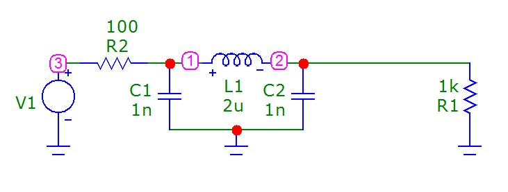
The resonant circuit can be simulated. It needs a load and signal source which is not a directly to C1 connected voltage source, something must be between to make C1 effective. I inserted a resistor in the next example. Transistor amp output is a current source.

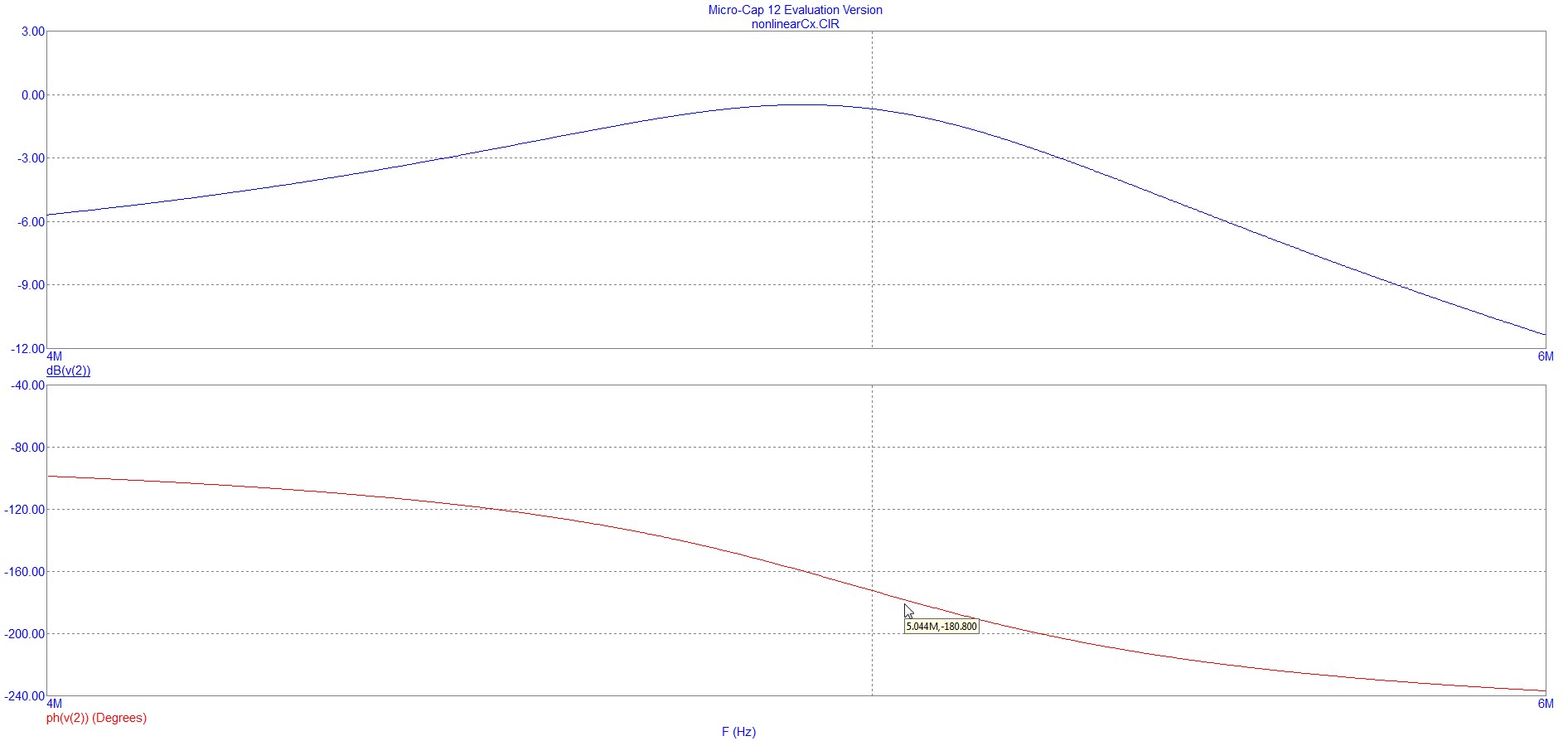
In the next example the resonant circuit attenuates the signal source voltage about 1dB at the frequency where the phase shift is 180 degrees - no problem to have an amp which amplifies enough for oscillation at few megahertz.

enter image description here

enter image description here

\$\endgroup\$
1
\$\begingroup\$

But I'm confused how can this oscillator provide a 360° degree turn for the input signal.

  • 180° comes from the transistor acting as an inverting amplifier.

  • About 170° comes from L and C2 so that accounts for 350°

  • About 10° comes from the output resistance of the collector and C1

  • Hence 360°

If you need maths let me know.

\$\endgroup\$
4
  • \$\begingroup\$ Yes, please. But if it has transfer function, please no since I won't understand it. And I also want to know why my analysis above does not have positive feedback \$\endgroup\$
    – hontou_
    Commented Aug 14, 2020 at 9:38
  • 3
    \$\begingroup\$ You are trying to analyse it from a start up transient perspective and this just isn't the right way to do it. Analyse it from a steady-state AC perspective as I have done. I've added links to the maths. \$\endgroup\$
    – Andy aka
    Commented Aug 14, 2020 at 9:44
  • \$\begingroup\$ Andy...I am afraid your update could cause some confusion because the feedback circuit shown in the box is not the same as in the question... it produces zero phase shift...but we require -180deg \$\endgroup\$
    – LvW
    Commented Aug 15, 2020 at 11:21
  • \$\begingroup\$ @LvW you're probably right, I'll delete the update and send a memo to myself to read questions more carefully in future! \$\endgroup\$
    – Andy aka
    Commented Aug 15, 2020 at 11:22

Your Answer

By clicking “Post Your Answer”, you agree to our terms of service and acknowledge you have read our privacy policy.

Not the answer you're looking for? Browse other questions tagged or ask your own question.