1
\$\begingroup\$

So, I want to make a High-Frequency Ferrite transformer that can convert my 150-volt peak Square wave into 100000 Volt Peak.

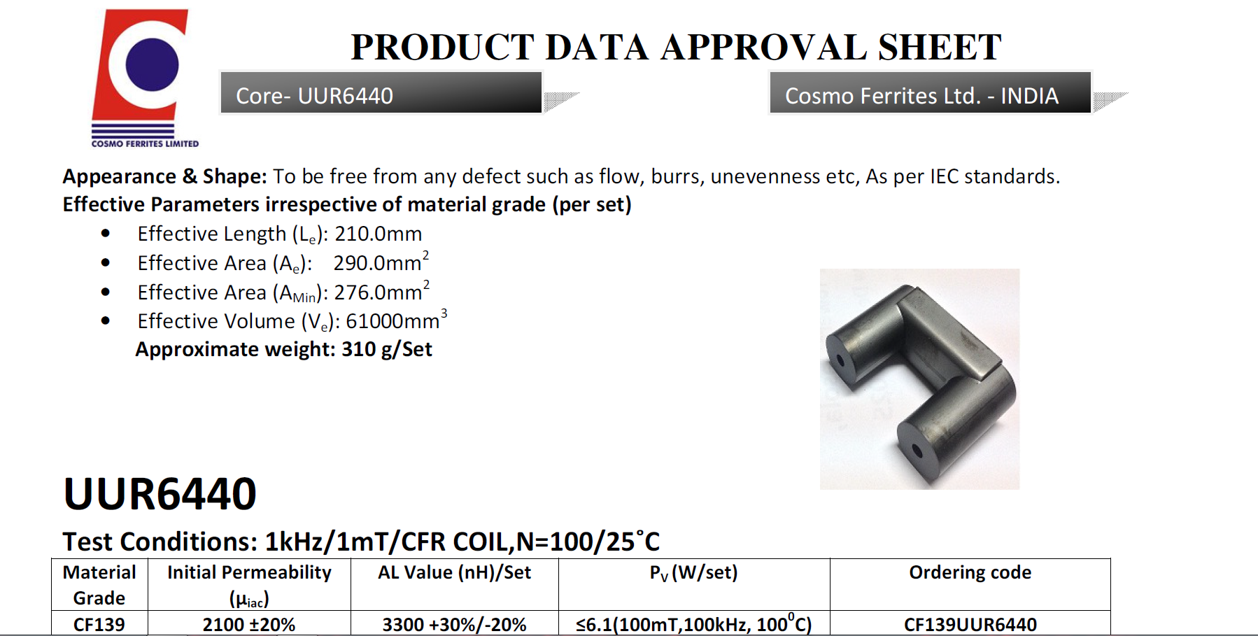
I am using UUR6440 Ferrite Core. Material is CF139

https://www.cosmoferrites.com/Downloads/Alnh/CF139.pdf.

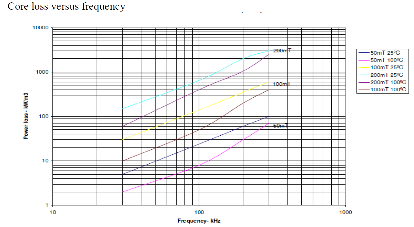
enter image description here

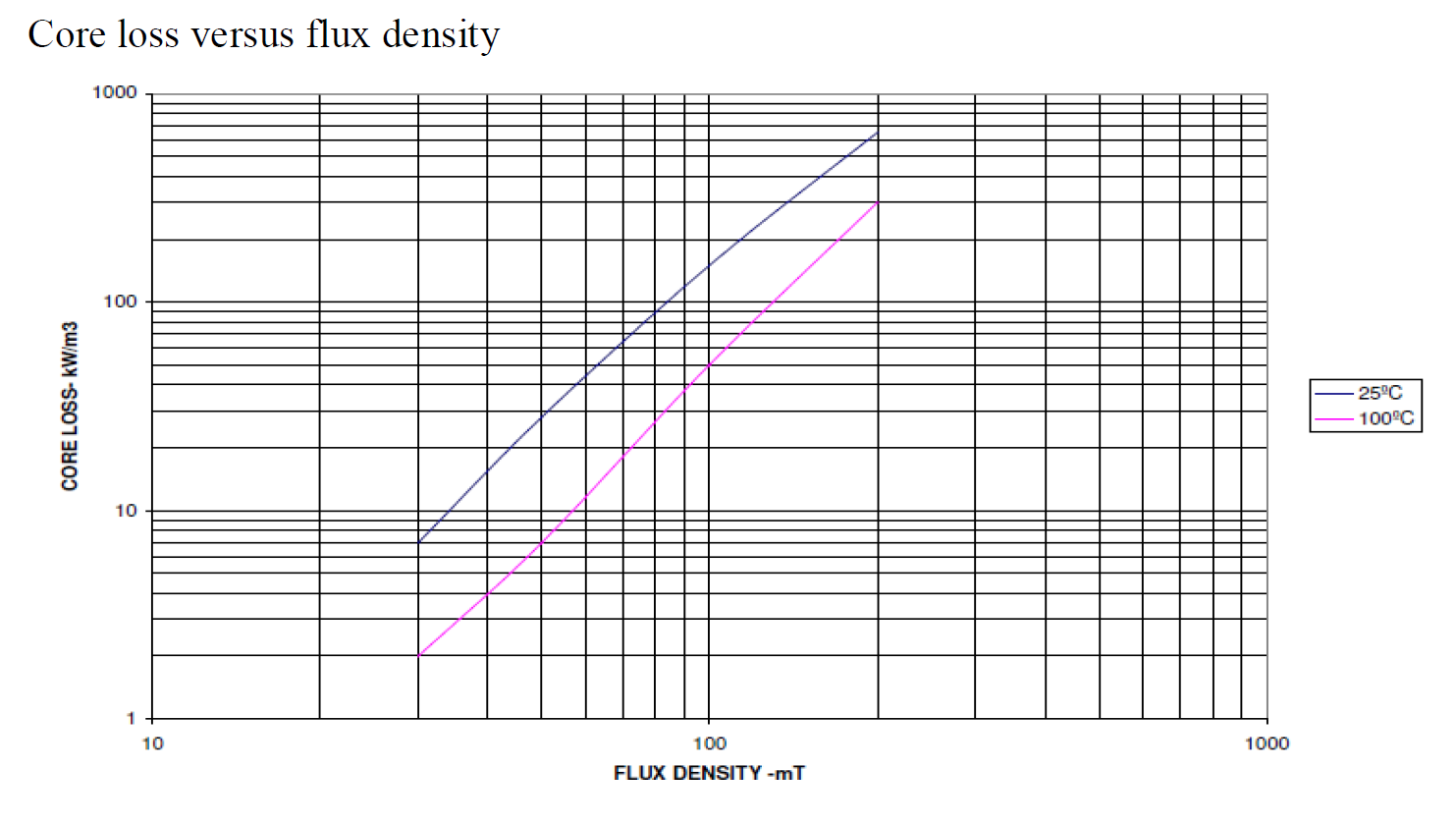
Below is the chart of the material. CORE LOSS VS FLUX DENSITY.

enter image description here My power supply setup is Half-Bridge topology for now. In the final design, I will use the H bridge. I have used 2* G4PC50UD Igbt to generate the Square wave.

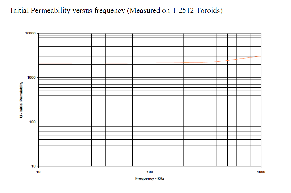
enter image description here

For my design, I have used Bmax as 35mT, or 3500 gausses. I have calculated primary using this formula.(0.5 * Vin * 10^8)/ 4 * F * Bmax * Cross-section-Area). I have added 0.5 cause my design is Half Bridge. My switching Frequency is 50Khz. And my cross-section area is 2.9cm^2. So the result is 3.69 turn, so have used 4 turns in primary using 6mm square Wire. I need not more than 28mA in Secondary, so I have used 37AWG wire. And the secondary turn I have calculated using *(Vs/Vp)Np= 2666 Turns in secondary. But I have used 3000 turns in secondary.

Now the problem I am facing is while my secondary is at 0/NO loads,my Primary current is drawing 15-ampere peak at 40 volts RMS. When I am trying to give more voltage in the primary, the primary is drawing more current proportional to the primary voltage. Even when I am trying to generate an ARC in secondary the primary peak current is the remain the same. At 40 volt RMS my secondary should generate 4*666.66 = 26640 Volt. But the arc is only 1cm Long. My power is supply can provide up to 3KW.

  1. So can I generate 100000 Volt at 28 milliamps using my current setup?

  2. Why my ferrite transformer drawing 15amp peak at 40-volt RMS at NO loads ?, I mean when the secondary is not generating any ARC or the secondary wires are not even close? I have measured the secondary wire resistance. The resistance is 535 ohms.

  3. If my calculation is all wrong what you suggest I should be doing to generate 100000 Volts at 28 milliamps?

schematic

simulate this circuit – Schematic created using CircuitLab

\$\endgroup\$
10
  • 1
    \$\begingroup\$ Please share your schematic. What have you simulated so far? \$\endgroup\$
    – winny
    Commented Aug 14, 2020 at 13:26
  • 1
    \$\begingroup\$ 35 mT is not 3500 Gauss. \$\endgroup\$
    – user16324
    Commented Aug 14, 2020 at 13:26
  • 2
    \$\begingroup\$ How is your secondary wound? How many layers, how many turns per layer, what thickness insulation between layers. Then we can do an order of magnitude calculation of the self capacitance of the secondary, which will probably help answer your questions. \$\endgroup\$
    – Neil_UK
    Commented Aug 14, 2020 at 13:27
  • 3
    \$\begingroup\$ Given the AL of the core, which estimates Lp at 53 uH, shows 15 A primary Ipeak is only a factor of 4 higher than what would be expected. Any extra airgap will reduce AL radically and increase current. It will be interesting to see whether you're operating above or below SRF. \$\endgroup\$
    – Neil_UK
    Commented Aug 14, 2020 at 13:32
  • 3
    \$\begingroup\$ Get the primary to behave first ... maybe with a 1:1 secondary for testing ... before you try winding 65000 turns! \$\endgroup\$
    – user16324
    Commented Aug 14, 2020 at 13:55

1 Answer 1

4
\$\begingroup\$

You are way-off in your expectations. The peak flux density you will see is over 7 teslas and that's about 15 to 20 times more than what ferrite can handle: -

  • Peak voltage = 150 volts
  • Inductance = 4 turns squared x 3300 nH = 53 uH
  • V/L = 2.83 amps per micro second
  • At 100 kHz (and 50% duty) the peak current is 14.15 amps
  • Magneto motive force (MMF) = amps x turns = 56.6 At
  • H = MMF / core effective length (0.21 m) = 270 At/m
  • B = μr μ0 H = 2100 * 4 π * 10^(-6) * 270 = \$\boxed{\text{7.125 teslas}}\$

Too much flux density by a mile for ferrite (normally limited to 0.4 teslas) and I'm not surprised you are seeing a massive current because the core is strongly saturating.

I've just noticed that your switching frequency is actually 50 kHz and this means my number for peak flux density is low by a factor of 2:1 (even worse).

If my calculation is all wrong what you suggest I should be doing to generate 100000 Volts at 28 milliamps?

If you are trying to get a 100 kV DC output then limit your transformer to producing an RMS output in the mid-kV range i.e. 3 to 5 kV AV and then use a Cockcroft-Walton voltage multiplier on the output that is oil-immersed and I don't mean cooking oil.

The reason I point out about limiting the transformer AC output is that with the number of turns needed, the insulation between secondary layer and the leakage inductance, you'll just about avoid hitting the self-resonant frequency of the transformer. If you hit SRF then you'll get really big problems that you'll never control.

$$\color{red}{\boxed{\text{Be aware - this sort of design can kill you in an instant}}}$$


I once designed a 50 kV power supply for an X-ray machine and plenty of days I got cold feet and stress during initial prototype testing. It could produce 4 mA but it was a scary beast. I had my load (and CW multiplier) immersed in a big oil bath and you could see the oil churning with the volts when I was operating at full wack. You should never do this on your own - you need someone in the room with you with a long stick that can press the on-off button on the DC power supply in case you start to fry.

\$\endgroup\$
7
  • 1
    \$\begingroup\$ Yup. 100kV and 28mA can kill you without touching, given long enough. And fog any photographic film in the area... \$\endgroup\$
    – user16324
    Commented Aug 14, 2020 at 14:00
  • 2
    \$\begingroup\$ I once designed a 50 kV power supply for an X-ray machine and plenty of days I got cold feet and stress during initial prototype testing. It could produce 4 mA but it was a scary beast. I had my load (and CW multiplier) immersed in a big oil bath and you could see the oil churning with the volts when I was operating at full wack. You should never do this on your own - you need someone in the room with you with a long stick that can press the on-off button on the DC power supply in case you start to fry. \$\endgroup\$
    – Andy aka
    Commented Aug 14, 2020 at 14:06
  • \$\begingroup\$ @Andyaka. Thank you for showing concerns regarding my safety. I have seen many youtube videos they are using ferrite transformer with IGBT , so how they generating 75 kV or above ?? are they generating less current than mine ?? or the voltage they say are generating is not true ?? \$\endgroup\$ Commented Aug 14, 2020 at 14:09
  • 1
    \$\begingroup\$ @EhsanHabib there is a lot of rubbish about electronics stuff on the internet and what appears to work and be good on day 1 (when they filmed it for youtube) may fail on day 2. Also low power stuff can make use of SRF of transformers but it has its dangers and reliability problems. \$\endgroup\$
    – Andy aka
    Commented Aug 14, 2020 at 15:15
  • 1
    \$\begingroup\$ $$V = L\dfrac{ΔI}{Δt}$$ Just re-arrange to solve for I. I will ramp up at so many amps per microsecond for 5 us then ramp down at same rate for 5 us. It tells you what the peak current is, That then allows you to calculate peak flux density via MMF and H-field. \$\endgroup\$
    – Andy aka
    Commented Aug 14, 2020 at 15:19

Your Answer

By clicking “Post Your Answer”, you agree to our terms of service and acknowledge you have read our privacy policy.

Not the answer you're looking for? Browse other questions tagged or ask your own question.