I wonder why are, e.g. when using a wheatstone bridge in combination with strain gauges, two of these SGs do have a positive k-factor and the other two a negative k-factor. Gladly, there is already How does full wheatstone bridge with strain gauges work? so I can realize the equation - but I lack something like a physical meaning of that concept. Is it possible to understand it despite of just the final equation? Does it make sense due to "common sense" somehow which I'm not aware of? And, btw, when these two pairs apparently behave counter-wise: Why is the resistance change not zero then in the end? That is, when R1 is increasing because the SG is lengthening, and R2 is decreasing, because the SG is shortening, then there should be no change in resistance at all, or? And vice versa to the other pair.
-
\$\begingroup\$ Here it is nicely animated: fh-aachen.de/fachbereiche/medizintechnik-und-technomathematik/… and - apparently - it is not of zero change. This is not intuitive for me. \$\endgroup\$– BenCommented Aug 18, 2020 at 12:12
-
\$\begingroup\$ If they all had a positive factor, wouldn't the bridge remain in balance and produce no output? \$\endgroup\$– user16324Commented Aug 18, 2020 at 12:45
-
\$\begingroup\$ I guess this is what I'm asking? \$\endgroup\$– BenCommented Aug 18, 2020 at 13:33
1 Answer
I wonder why are, e.g. when using a wheatstone bridge in combination with strain gauges, two of these SGs do have a positive k-factor and the other two a negative k-factor.
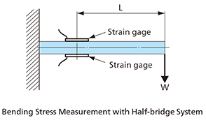
A typical example is on a cantilever beam where a strain gauge on the upper surface is matched by a strain gauge on the lower surface. When the beam is bent upwards the upper gauge is compressed and lowers its resistance whilst on the underside, the gauge is stretched and increases its electrical resistance: -
Why is the resistance change not zero then in the end? That is, when R1 is increasing because the SG is lengthening, and R2 is decreasing, because the SG is shortening, then there should be no change in resistance at all
Absolutely correct but, that is of little importance given that we are largely uninterested in the top to bottom net resistance of the bridge; what we are interested in are the voltage changes at the midpoints of each limb due to (a) resistance lowering on the compressed gauge and (b) resistance increasing on the stretched gauge.
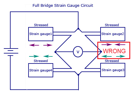
I think I see where your diagrams have confused you - basically, the RH diagram is wrong as depicted below: -
The upper right should be in tension and the lower right should be in compression to make it work properly.
-
\$\begingroup\$ Thanks a lot for the answer! To make clear: R1 and R4 have always the same voltage together as R2 and R3, or? I can't quite follow why that diagram is wrong. I thought, e.g., when using four SGs, then the two are in different voltage dividers of that full bridge. At least it is so according to here: fh-aachen.de/fachbereiche/medizintechnik-und-technomathematik/… \$\endgroup\$– BenCommented Aug 18, 2020 at 13:38
-
-
1\$\begingroup\$ Why should the right be the same as the left? Wouldn't that result in no net voltage? \$\endgroup\$ Commented Aug 18, 2020 at 13:53
-
1\$\begingroup\$ These arrows are rather confusing. What are color and arrow direction even supposed to mean? \$\endgroup\$ Commented Aug 18, 2020 at 14:04
-
\$\begingroup\$ @Ben for equal strains and same gauge devices, R1 and R4 will have same voltage and that must mean R2 and R3 have same voltage. Is that what you asked about? \$\endgroup\$– Andy akaCommented Aug 18, 2020 at 14:27


