2
\$\begingroup\$

Ok, I will try to keep it as short as possible.

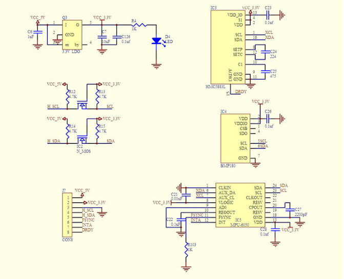
I have a GY-86 breakout board, the schematic is added below. As seen, MPU6050 and BMP180 are connected on the same I2C bus.

enter image description here

I do also have an Arduino. So, master is Arduino and the slaves are MPU6050 and BMP180.

I have used a premade I2C scan sketch with my Arduino, and the output is:

13:50:00.731 -> Scanning...
13:50:00.731 -> I2C device found at address 0x68  !
13:50:00.764 -> I2C device found at address 0x77  !
13:50:00.797 -> done

This is fine, since 0x68 is MPU6050 and 0x77 is BMP180. So, both slaves respond to address check. However, while MPU6050 is fully functional, i.e I can get data from it, BMP180 is not responding. I have used several premade "get BMP180 data Arduino code" from the internet, and none of them worked.

I also have an STM32 MCU, when I use it as master insted of Arduino, same story happens. Despite using the same I2C read/write functions, MPU6050 readings/writings are totally fine, but I cannot write to or read from BMP180. By debugging, I found that AF(acknowledge failure) flag is set when the MCU stucks while trying to write/read BMP180.

I also examined datasheets of both sensors several times, they seem to have the same I2C read/write pattern.

In short, somehow, BMP180 is found on I2C line by the I2C scanner, but data read/write cannot be done. What could be the reason for that? I could assume I somehow dameged BMP180, but it replies to its address. So, I could not understand what is going on. Any idea would be appreciated.

\$\endgroup\$
2
  • 1
    \$\begingroup\$ sometimes, the working module is actually the defective one ... perhaps, both modules are supposed to fail \$\endgroup\$
    – jsotola
    Commented Aug 22, 2020 at 20:43
  • \$\begingroup\$ @jsotola interesting point :) \$\endgroup\$
    – muyustan
    Commented Aug 22, 2020 at 20:45

2 Answers 2

1
\$\begingroup\$

The fact the BMP180 is responding to address check does not indicate it is working properly. Before using the chip, did you check the max voltage allowed on the pins? It looks be a hardware problem. Did you try to use other BMP180?

\$\endgroup\$
4
  • 1
    \$\begingroup\$ no, I don't have another one, unfortunately. \$\endgroup\$
    – muyustan
    Commented Aug 22, 2020 at 18:58
  • \$\begingroup\$ I know it's so hard to get a hand on these sensors. I had to buy already made boards from ebay and desolder the chips because they are not produced anymore. If you have experience with electronics I would highly encourage you to walk away from chips that are no longer produced. If not, bmp180 is a cool thing to learn. \$\endgroup\$
    – bem22
    Commented Aug 22, 2020 at 19:03
  • \$\begingroup\$ @bem22 these parts come from china in almost a month or even longer, it is so sad if the sensor is damaged \$\endgroup\$
    – muyustan
    Commented Aug 22, 2020 at 19:05
  • \$\begingroup\$ It depends where you buy them from. Check Mouser/Digikey/Farnell. I know bmp180 is hard to find (from experience) :( \$\endgroup\$
    – bem22
    Commented Aug 22, 2020 at 19:06
1
\$\begingroup\$

I have used this exact schematic in my project. It is possible that one of your i2c devices responds to 3V3 and the other one to 5V. I have never ended up using the N_MOS 5V to 3V3 signal converter (not worth it). All devices will work on 3V3 bus with no problem. I highly recommend simplifying the circuit and using the 3V3 only.

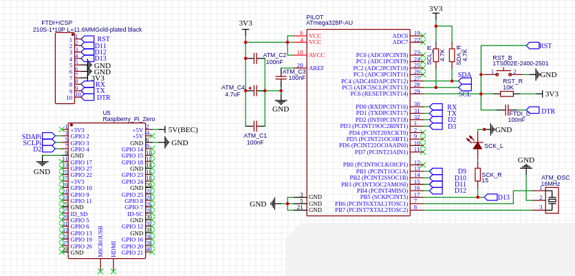
Also, make sure you have the right resistors for your microcontroller on the SDA/SCL busses (see SCL_R/SDA_R in picture 2)

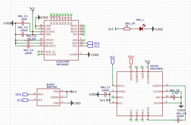
Take a look at my schematic: I decided to eliminate the N_MOS'es for both SCL and SDA. enter image description here enter image description here

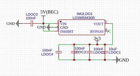
And here is the power supply: enter image description here Have a look at my project here: https://easyeda.com/be.mihai22/project-hawk

Btw, here's a demonstration that the drone actually works.

\$\endgroup\$
4
  • \$\begingroup\$ hey, thanks for the answer. I also am working on doing a flight controller, I will check your project. Did you buy 3 sensors as discrete parts and connected them on your own? I am not using +5V anywhere, all my powerings etc. are 3.3V. I also don't think there is a problem related to pull up resistors because MPU6050 works just fine. \$\endgroup\$
    – muyustan
    Commented Aug 22, 2020 at 19:02
  • \$\begingroup\$ If you used that schematic with all the parts in there, you should have (in theory) used 5V somewhere. Yes, this was my disertation project (a drone and flight controller). I have both the GY-88 chip (from ebay or amazon something) and I have also soldered all the components from 0 to a new PCB. Look at the project on easyeda. Also I would highly recommend you check out the datasheets of the two sensors \$\endgroup\$
    – bem22
    Commented Aug 22, 2020 at 19:05
  • \$\begingroup\$ I don't know the board I have is exactly wired as in that schematic, but probably. I don't connect +5V to VCC_5V pin of the GY-86 board, so I don't think I have +5V at anywhere. I power it through VCC_3.3 pin \$\endgroup\$
    – muyustan
    Commented Aug 22, 2020 at 19:07
  • \$\begingroup\$ Post a picture of your circuit (real circuit). \$\endgroup\$
    – bem22
    Commented Aug 22, 2020 at 23:11

Your Answer

By clicking “Post Your Answer”, you agree to our terms of service and acknowledge you have read our privacy policy.

Not the answer you're looking for? Browse other questions tagged or ask your own question.