13
\$\begingroup\$

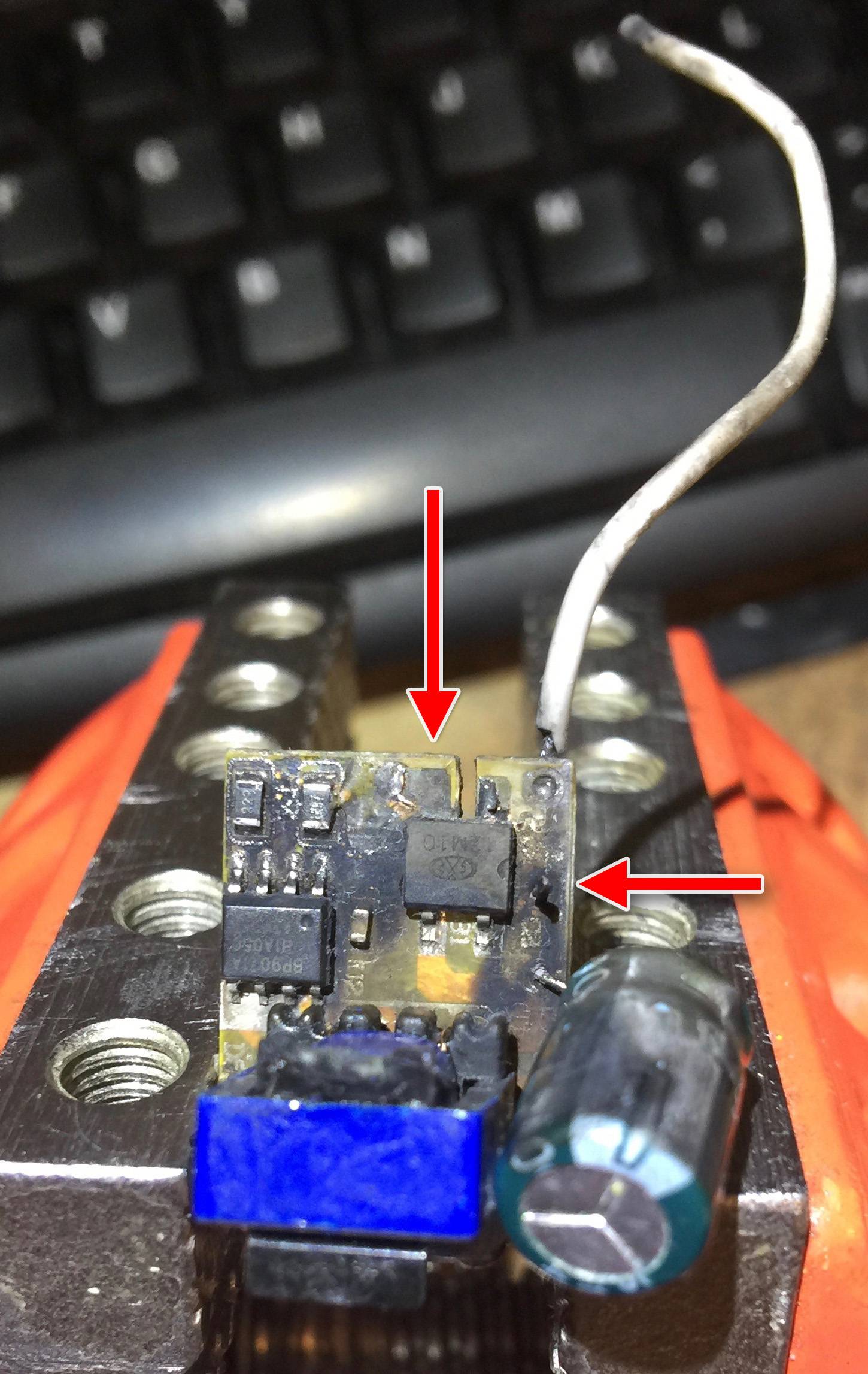
This LED drive module exploded last night, as the result of an earthed (grounded) screw touching a capacitor leg. The breaker (fuse box) tripped, of course, due to earth leakage. That bit makes sense.

What I don't get is why there was a massive bang, a flash, tracks blown off the board and soot all over the place. Of course, this is not unusual in mains power faults, but in this particular case, the short appears to have been between neutral and ground.

I like to think I have a fairly good understanding of electricity, but given that neutral is connected to ground at the fuse box, I don't see how a large enough voltage should develop between the two (in this situation) to cause such devastation.

For bonus points, can you think of any good reason that a completely different piece of equipment (an electronic HDMI switchbox) should now be completely nonfunctional after the above incident? It was powered via an isolated wall-wart, and was completely unrelated to the device that exploded, other than being located within two feet of it.

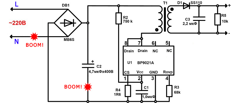
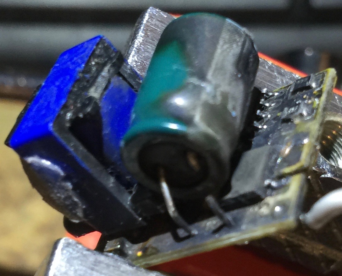
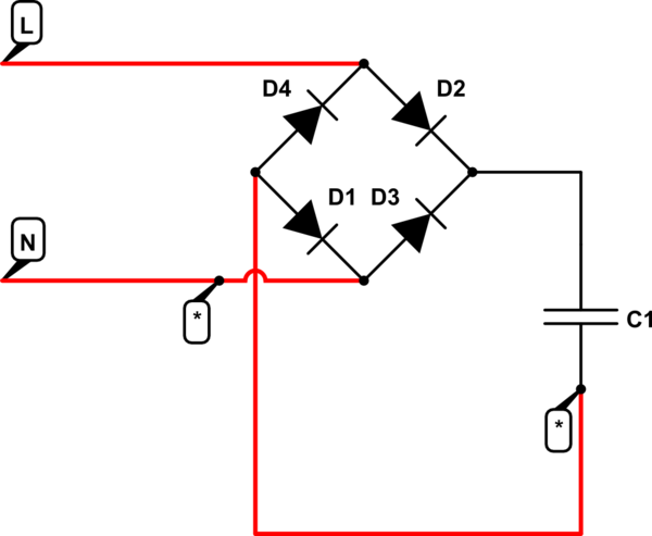
Photos and (best as I can tell) the correct circuit diagram follow.

diagram

photo 1

photo 2

\$\endgroup\$
3
  • 2
    \$\begingroup\$ Oh, Soot Almighty! \$\endgroup\$ Commented Sep 9, 2020 at 19:10
  • \$\begingroup\$ "can you think of any good reason that a completely different piece of equipment (an electronic HDMI switchbox) should now be completely nonfunctional after the above incident" Blown fuse? \$\endgroup\$
    – Lundin
    Commented Sep 10, 2020 at 12:47
  • \$\begingroup\$ Nope. The power light lights up (so I guess it depends how you define "completely nonfunctional" I suppose) but nothing operates on the unit. \$\endgroup\$ Commented Sep 10, 2020 at 19:20

4 Answers 4

27
\$\begingroup\$

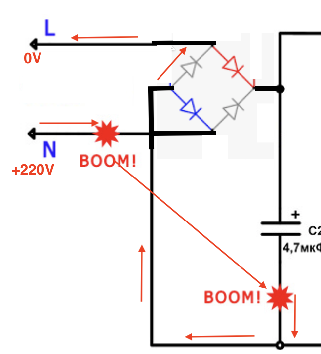
The bottom of C2 is not ground. It is connected to the live input by the diodes in the bridge rectifier on every AC cycle.

During the negative half-cycle of the incoming AC waveform, the Neutral wire is positive relative to the live wire.

The two grey diodes in the diagram below will be conducting for this half cycle, the other two conduct during the other half cycle.

The Neutral is connected to the protective ground at the circuit breaker panel (depending upon the local electrical codes). So AC power earth and the neutral line are effectively the same point electrically.

The neutral wire (or earth) where the short circuit occurred will have a voltage (up to ~300V) relative to the bottom pin of the capacitor.

The screw caused a short circuit between these two points and caused a large current to flow along the path of the red arrows causing the upper-left blue diode to be destroyed.

During the other half cycle of the input waveform, the voltage between the two shorted points will only be ~0.7V across the already conducting lower-left grey diode. No damage will result as a result of the short-circuit.

enter image description here

You should always be very careful when testing or inspecting a device such as this - there is no point that is ground.

If for example, you connect a grounded instrument such as a scope you can cause a similar destructive short circuit.

It is common for the power supplies to be organized similarly, computers, TVs, DVD players etc.

\$\endgroup\$
12
  • \$\begingroup\$ Ah. So you mean during those parts of the waveform that live is negative, there is a 240V potential difference between the bottom of the cap and earth, the cap being negative with respect to earth? \$\endgroup\$ Commented Sep 9, 2020 at 20:18
  • \$\begingroup\$ Actually it is worse than that and for parts of the cycle it is more than 300V for a 220V RMS input. \$\endgroup\$ Commented Sep 9, 2020 at 21:14
  • \$\begingroup\$ I've just realised your answer - while interesting - doesn't explain the entire situation. If you look at the photo, it's the neutral leg of the rectifier that blew off. If the short was between earth and live (during the negative part of the cycle), why did we lose the neutral leg of the rectifier while the live leg survived? \$\endgroup\$ Commented Sep 10, 2020 at 19:37
  • 1
    \$\begingroup\$ @SodAlmighty, in an energized AC circuit, there is no "line" or "neutral" wire. There are only "live" and "live" wires. It's only when you've got a gap in the circuit that it matters which wire is being driven by the generator. \$\endgroup\$
    – Mark
    Commented Sep 10, 2020 at 20:40
  • \$\begingroup\$ @SodAlmighty - I've added more detail to my answer. \$\endgroup\$ Commented Sep 10, 2020 at 20:42
15
\$\begingroup\$

you can call it ground, but it's not actually ground. It's actuallty the negative output of the bridge rectifier.

schematic

simulate this circuit – Schematic created using CircuitLab

That short circuit allows a large current to flow in D4

Boom!

\$\endgroup\$
7
  • 1
    \$\begingroup\$ It seems to me that the large current flow passes through all four diodes, two of them in positive part of AC cycle, the other two in the negative part of AC cycle. \$\endgroup\$
    – mguima
    Commented Sep 9, 2020 at 19:08
  • 1
    \$\begingroup\$ the other diodes always have one blocking the large current \$\endgroup\$ Commented Sep 9, 2020 at 19:09
  • \$\begingroup\$ @mguima No. In the negative part of the cycle, it flows through D4 only, toward L. In the positive part, it flows normaly, but in this case the circuit breaker already tripped. \$\endgroup\$
    – Fredled
    Commented Sep 9, 2020 at 22:19
  • 1
    \$\begingroup\$ @Jason, I love the way that your post says "Simulate this circuit [...] BOOM". \$\endgroup\$ Commented Sep 10, 2020 at 7:09
  • \$\begingroup\$ For clarity, the part of the N wire to the right of the dot should be coloured black. \$\endgroup\$ Commented Sep 10, 2020 at 10:51
1
\$\begingroup\$

Regarding the second part of the question, the now broken HDMI electronic box, my first thought would be that it is a totally unrelated event, but discovered at a later time. The only other plausible hypothesis concerns an overvoltage due to the transient following the intervention of the circuit breaker or the subsequent reset, but it's very unlikely.

\$\endgroup\$
4
  • \$\begingroup\$ I wonder if the short caused a momentary, and localised change to the AC waveform in the HDMI's wallwart - presumably not the greatest quality PSU - which caused it to fail, or blow a fuse or whatever...? Still seems a bit of a reach though. \$\endgroup\$ Commented Sep 10, 2020 at 16:18
  • \$\begingroup\$ It was discovered immediately, as I use the HDMI switch all day every day. And it's not a fuse issue. Power is reaching the unit (power light is illuminated) but no functionality of any kind. No status lights, no HDMI throughput. And, interestingly, the wall-wart power supply still works, and will power my other HDMI switchbox. Which also still works... \$\endgroup\$ Commented Sep 10, 2020 at 19:23
  • \$\begingroup\$ I absolutely believe you about the time of discovery. These effect of transients are sometimes very chaotic. Without some circuit analysis, we can't even know if the energy surge that broke your apparatus traveled along wires or in the air. \$\endgroup\$
    – DrSurfer
    Commented Sep 11, 2020 at 9:48
  • \$\begingroup\$ First, the damaged HDMI Box could easily be damaged by the triggering of the fuse. If any circuit after the fuse has stored energy or the fuse triggered too slow (fault), it will cause such issues. and most (cheep) consumer parts will not have sufficient surge protection. back to number one, the blown LED drive module - the contact with earth might not have been perfect (higher resistance), so the Fuse was triggered by time not by peak current. Or it first triggered after the burnings (coal is a better conductor). \$\endgroup\$
    – schnedan
    Commented Sep 11, 2020 at 20:07
-1
\$\begingroup\$

Because it was probably plunged in the 220VAC socket and you can twist around. How do you know that L was connected to line and N to neutral?

\$\endgroup\$
9
  • 6
    \$\begingroup\$ But a circuit like this would bang the same way, whatever was the Live and Neutral connection, doesn't matter if the plug was twisted or not. \$\endgroup\$
    – mguima
    Commented Sep 9, 2020 at 19:05
  • \$\begingroup\$ @mguima Yes you are correct. The cap potential is cca +160 VDC or -160 VDC whatever position you plug in. Make your answer. \$\endgroup\$ Commented Sep 9, 2020 at 19:09
  • 1
    \$\begingroup\$ @MarkoBuršič because I live in the UK, where matters of electrical safety are taken seriously. It is physically impossible to plug appliances in backwards. \$\endgroup\$ Commented Sep 9, 2020 at 20:20
  • 2
    \$\begingroup\$ @SodAlmighty If it weren't for The Channel, my country would neighbor yours. We have different plugs, but ours are also impossible to plug in backwards. But... that has nothing to do with reverse polarity. Because with AC... there is no polarity. Flipping the L and N in an appliance (important distinction! ), will not affect its workings whatsoever. So in your schematic, L and N could have well been reversed without you knowing it. It didn't matter anyhow. relative to each other, they would have been the same. \$\endgroup\$
    – Opifex
    Commented Sep 10, 2020 at 6:55
  • 2
    \$\begingroup\$ -1 Doesn't make any sense for the circuit in question. The short wasn't to ground, but to the negative DC rail. \$\endgroup\$
    – TooTea
    Commented Sep 10, 2020 at 10:11

Your Answer

By clicking “Post Your Answer”, you agree to our terms of service and acknowledge you have read our privacy policy.

Not the answer you're looking for? Browse other questions tagged or ask your own question.