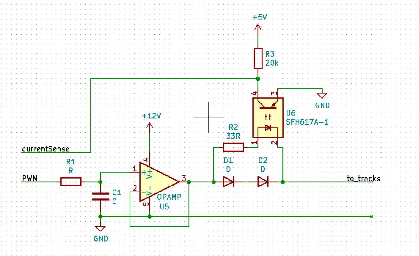
I have a question, an easy one I believe. I am designing a small module which may take control of an analog model train as soon as the train is detected.
When the train is detected, a uController must screw down the dutycycle to either 50% or 0% (frequency is fixed) to slow the train dowm to either half speed or a full stop
The voltage on this piece of track has to be analog (0V - 12V). Use of an unfiltered PWM signal on the tracks is not an option. The first section would be 12V DC, if a train would transition from the first section onto a section which has PWM every conducting wheel might trigger a short circuit spike between 0V and 12V. The system might get away with such short circuit spikes, but I believe it cannot possibly be any good and therefor I consider it a bad option.
Also driving analog trains with PWM is very undesirable. 1st digital trains do not understand a PWM signal and they will simply not work. It is common for people to have a digital train driving around among analog trains.
PWM'ing a train can be done on 20kHz or above (due to horrible high pitch sounds). This has horrible driving qualities on analog trains. Digital trains do use these frequencies, but these trains also come with cruisecontrol and an advancde PID (or something similars) system to deal with this.
By far the best way to achieve a good PWM controller is by varying the frequency alongside the dutycycle. < 10% Dutycycle you use 20Hz and 100% dutycycle is done @ 100Hz. Though trains drive wonderful on this method. The train's LED may flicker like an Xmas tree (glowbulbs work fine though) and sadly not every train has room to accomodate an anti flicker circuit. It is also not desirable if you need to do this with every train.
The detection is done via an optocoupler. When a current flows through the 2 diodes, they create a 1.4V drop over the led of an opamp which then pulls the currentSense line down to 0V. This informs the uController that a train has entered the section.
This circuit is designed for oneway traffic.
The opamp should correctly filter the pwm to an analog voltage. But I want it to drive a load of about 0.7A max without experiencing a noticeable voltage drop.
At the moment I have a rail to rail opamp in supply, but it cannot provide the desired 700mA.
Questions:
- Disregarding any potential heat development, can I simply add a mosfet or a transistor such as the TIP120 darlington behind the opamp without screwing up the voltage level on the tracks? Or will this affect the voltage level in a negative way (which I suspect)
- Is it a good idea to pick a stronger opamp such as this one from Mouser which can drive up to 1A
- Is it a good idea to use this circuit (with 5V instead of 12V) to 'replace' the potentiometer of an existing buckconverter (essentially I'd be controlling the output of a buck converter using this circuit as input)
Also. I am yet to learn how to run a simulation of a schematic, so no I have not simulated anything.

