2
\$\begingroup\$

I'm trying to understand what an IV plot of a memristors tells me in terms of physical properties. So these are the questions with the relevant plots:

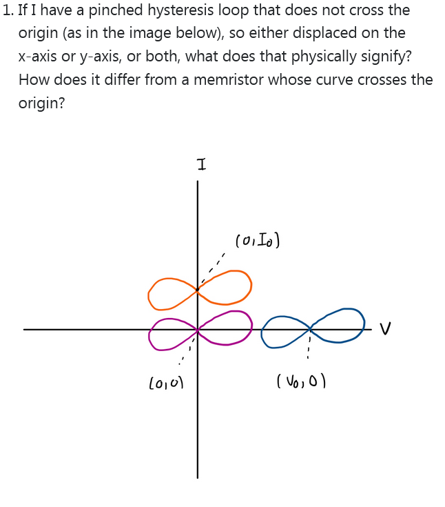
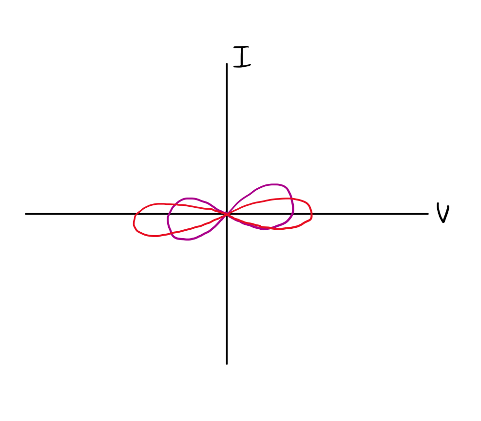
  1. If I have a pinched hysteresis loop that does not cross the origin (as in the image below), so either displaced on the x-axis or y-axis, or both, what does that physically signify? How does it differ from a memristor whose curve crosses the origin?

enter image description here

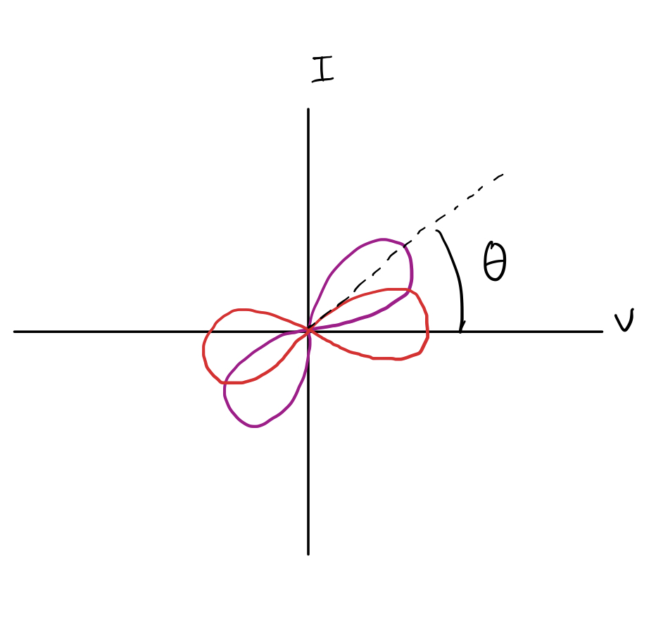
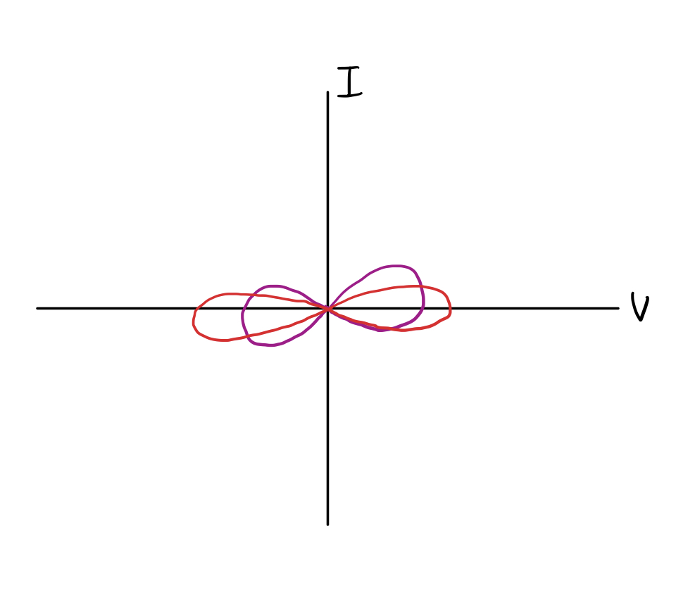
  1. How does a tilted pinched hysteresis loop differ in physical properties from one that is not titled? What does a rotation/tilt by an angle theta physically signify for a memristor ?

enter image description here

  1. What does the area of a pinched hysteresis loop resemble - if my input variable is voltage (so a voltage controlled memristor)? And what do different area values signify in terms of physical properties of memristors? And what is the effect of scaling on the physical properties of a memristor?

enter image description here

These are more generic questions that I am not sure of and I am not able to find answers to in the original Chua paper, answers or suggested references would be very helpful. Thanks in advance!

\$\endgroup\$
1
  • 1
    \$\begingroup\$ If the I-V-curve doesn't go through the origin, you have an energy generator. \$\endgroup\$
    – tobalt
    Commented Dec 12, 2022 at 10:43

2 Answers 2

1
\$\begingroup\$

If I have a pinched hysteresis loop that does not cross the origin (as in the image below), so either displaced on the x-axis or y-axis, or both, what does that physically signify? How does it differ from a memristor whose curve crosses the origin?

It means you have a constant voltage or current offset and it looks like this in a circuit (this does not happen with real memristors with real resistive materials AFAIK, I know there are no materials that you can build in a constant current offset (obviously), maybe a constant-ish voltage drop) :
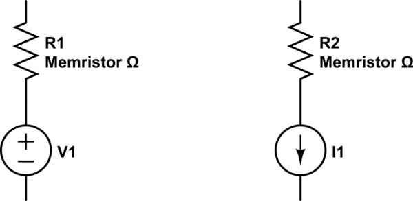
schematic

simulate this circuit – Schematic created using CircuitLab

How does a tilted pinched hysteresis loop differ in physical properties from one that is not titled? What does a rotation/tilt by an angle theta physically signify for a memristor ?

Well, I think you have to have some kind of tilt for it to be a memristor, otherwise it would be a voltage source with no current and only producing voltage at that point, and that wouldn't make sense physically, as the resistor would be producing voltage with no current, usually resistive materials produce a voltage after current . I suppose an ideal memristor could have no tilt. Real curves look like these and I haven't seen one that doesn't always have resistance:
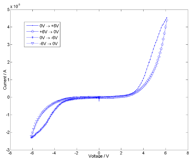
enter image description here
Source: Figure 3-My, and others’, spiking memristors are true memristors: a response to R.S. Williams’ question at the New Memory Paradigms: Memristive Phenomena and Neuromorphic Applications Faraday Discussion

The tilt is a resistance offset. You could think of it as adding a resistor to the no-tilt situation. You can see here resistance lines drawn for 0.5Ω, 1Ω and 2Ω resistors on the same plot.
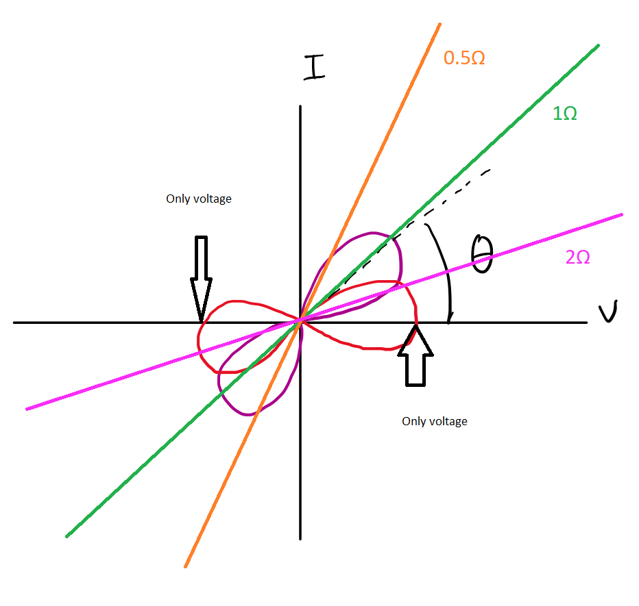
enter image description here

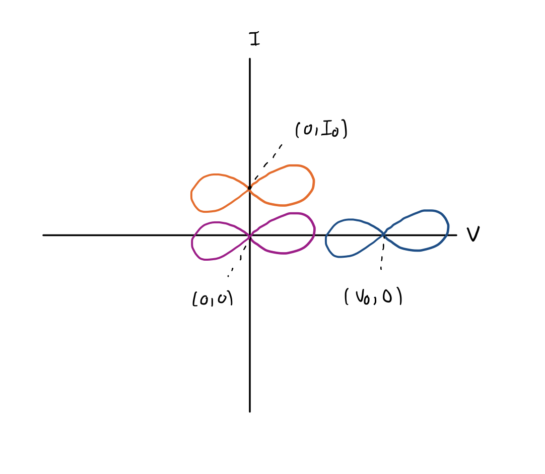
What does the area of a pinched hysteresis loop resemble - if my input variable is voltage (so a voltage controlled memristor)? And what do different area values signify in terms of physical properties of memristors? And what is the effect of scaling on the physical properties of a memristor?

It means that the resistance changes more, the area under the curve would represent power, so it would mean a bigger power change. I don't think this would make much sense to calculate the area under the curve. One thing that would make sense is to compare a larger loop vs a smaller loop because the farther the sides of the loop is from the other side the easier it is to detect a voltage and determine if the resistance is large or small (a 1 or 0 maybe).

\$\endgroup\$
2
  • \$\begingroup\$ I don't think there's anything inconsistent about having a voltage with zero current--this is true of capacitors, for instance. But such a device would necessarily be something more like a memristor in parallel with a capacitor or something like that, rather than a pure memristance. \$\endgroup\$
    – Hearth
    Commented Dec 10, 2022 at 20:32
  • \$\begingroup\$ Good point. That's true for ideal circuits, but for real materials the capacitance voltage bleeds off (think DRAM cells), and materials testers would not want to include series capacitance in the IV curves. \$\endgroup\$
    – Voltage Spike
    Commented Dec 10, 2022 at 21:05
0
\$\begingroup\$

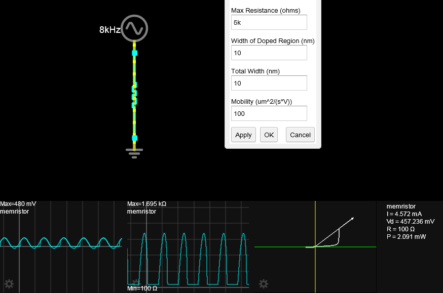
enter image description here

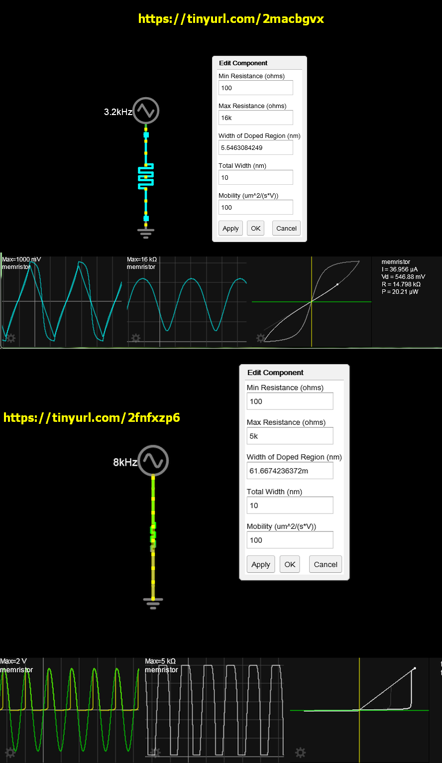
That physically means you do not have a memristor which have passive magnetic properties that are symmetrical in polarity. That is until a threshold voltage then they conduct heavily and behave like linear resistance until the polarity is sufficient reversed. This creates a pulsed current with a linear R on voltage modulation until 0V then high impedance again on negative polarities.

The dynamic range of resistance depends on the physical properties of the doped region in length and width in nm. the area of the curve maximizes memory from hysteresis whereas a resistor has no VI loop area.

So excessive voltage will cause the spike property. Seen below with excess voltage. enter image description here

Yet a capacitor and a diode have this similar property or a diode partially blown by ESD with lower R and higher C from the small gap. LEDs have this property when wounded by ESD but still work.

Adding DC bias does not simulate your hypothetical question as the amount of heavy conduction and nonlinear spike current requires a certain percentage of negative bias to regain the positive VI memory loop.

V = X axis , I = Y axis vertical.

enter image description here

  1. Theta increases with conduction [S] since the slope represents mean resistance V/I=R . Higher conduction occurs with higher voltage and current until the breakdown voltage trigger level is reached then causes spike current. This is physically determined by geometry of the gap size and doping thickness.

You can see this on my simulation but the plot needs to be manually resized if spike response occurs.

3.

What about area or ellipical shape as you showed.

enter image description here

The area is proportional to the magnetic constant of partial permeability or the hysteresis of margin from detecting current during rising and falling voltage.

But stretching the ellipse does not change the area so that does not show any memory gain margin.

Other opinions

OTP programmable static memories have a dynamic ratio of impedance of over 5 decades that depend on almost zero leakage current integrated over 10 years. While Memristors have a practical dynamic range of 2 to 3 decades and an inherent junction capacitance that limits frequency response to several decades below semiconductor OTP memory or EPROM due to the 2 or 3 orders of higher resistance.

\$\endgroup\$

Your Answer

By clicking “Post Your Answer”, you agree to our terms of service and acknowledge you have read our privacy policy.

Not the answer you're looking for? Browse other questions tagged or ask your own question.