2
\$\begingroup\$

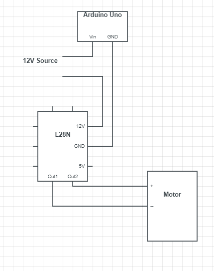
I'm quite confident the wiring of my motor-motor controller-Arduino setup is correct. I'm using an L28N H-Bridge motor controller and tested the output voltages to be correct (with 12V input). However, plugging this setup to my motor caused the motor to rotate slightly and the motor controller to overheat.

I disconnected this circuit and connected my motor to a 9V battery for testing. Under load, the voltage across the battery drops from 7.8V to 0.6V and the current is 1.6A, which I'm quite sure is way too high, since the battery was warming up.

My motor controller is only rated for 5-46V and 2A output, and I'm limited on the specs of the motor. What can I do?

L28N MotorController

enter image description here

EDIT: Received the robot details: https://www.banggood.com/Upgraded-WT-500S-Smart-RC-Tracked-Tank-RC-Robot-Car-Base-Chassis-p-1360827.html?gmcCountry=US&currency=USD&createTmp=1&cur_warehouse=CN

\$\endgroup\$
6
  • 1
    \$\begingroup\$ You need to specify the exact motor type and include a data sheet for the motor + driver. Please also draw a schematic of your connections. \$\endgroup\$ Commented Sep 29, 2020 at 17:17
  • \$\begingroup\$ Done. No motor data sheet on hand though. The motor runs a tread-type wheel for a reasonably heavy (10+ lb) robot. \$\endgroup\$
    – thugzook
    Commented Sep 29, 2020 at 17:38
  • 1
    \$\begingroup\$ @thugzook In that case the motor drawing too much current for the system. The L298N is not an efficient driver. It will get warm even with a light load. \$\endgroup\$
    – Drew
    Commented Sep 29, 2020 at 17:43
  • \$\begingroup\$ There's no sensible way to power 1A+ from a 9V PP3 battery. \$\endgroup\$
    – user16324
    Commented Sep 29, 2020 at 18:21
  • \$\begingroup\$ I didn't specify. My actual power source is a 14V, 4 cell Li-Po battery with a max current draw of 165A \$\endgroup\$
    – thugzook
    Commented Sep 30, 2020 at 14:54

1 Answer 1

1
\$\begingroup\$

The reason your measured voltage drops significantly is the internal resistance of your battery. A 9V alkaline can't source much current, definitely not the 1.6A your motor would like. I'd be curious to know what you measure if you do the same test, substituting the 9V for 6 AAs.

Also, I'm sure your schematic is simplified, but are you using flyback diodes on your controller? Leaving them out leaves the L298 vulnerable to back emf from your motor. If not, it's probably burnt out already, which would explain some of the behavior you listed. Page 6 on your pdf has an example of the diodes.

\$\endgroup\$
1
  • \$\begingroup\$ With this information, my buck converter has a max current draw of 3A, my motor controller has a max of 2A and the robot is something of ~8A. Would a flyback diode fix my problems or would I need better hardware for both parts? As of right now, it's just connected straight to the motor, as I've seen in other schematics \$\endgroup\$
    – thugzook
    Commented Sep 30, 2020 at 15:05

Your Answer

By clicking “Post Your Answer”, you agree to our terms of service and acknowledge you have read our privacy policy.

Not the answer you're looking for? Browse other questions tagged or ask your own question.