I'm supposed to use a TMP36 transistor for a class to read the temperature of the environment, but I only have a 2N2222 transistor; the Arduino will have an analog read of it, but the numbers won't change even if I heat it up. Am I screwed or can I fix this?
-
11\$\begingroup\$ A TMP36 is not a transistor, so there is no way to substitute it with a 2N2222 which will give you useful results. \$\endgroup\$– brhansCommented Oct 4, 2020 at 2:12
-
5\$\begingroup\$ @John Rawls, Ah yes, you can turn 2N2222 into a TMP2222 for your class to read temperature of the environment. The problem is that Arduino ADC is only 8 bit so it is not precise enough to detect the small 2N2222 characteristic differences (eg, hFE, Ic etc) as temperature changes. A workaround is to use a dirt cheap 10bit/12bit ADC such as MCP3008/MCP3201/MCP3208 which enable you to read 0.!% to 0.025% accuracy. Then you need a thermometer to calibrate the hFE/Ic vs temperature graph. The graph might not be that linear. But / to continue, ... \$\endgroup\$– tlfong01Commented Oct 4, 2020 at 3:12
-
3\$\begingroup\$ / continue, ... you can show your class that you are an innovative future engineer, and of course they would see you as a hero, and your teacher couldn't resist to give you a A grade, and your school principal to give you an outstanding R&D academic award, Then your principal can write to Analog Device about your fake TMP36 studies, and request them to give your class 40 real TMP transistors to do real research. :) \$\endgroup\$– tlfong01Commented Oct 4, 2020 at 3:17
-
2\$\begingroup\$ Vbe of the transistor depends on temperature in a fairly predictable way. Using a diode or base-emitter junction as a temperature sensor is a fairly common application. Spehro already answered, though, so I won't write another answer saying the same thing. \$\endgroup\$– user57037Commented Oct 4, 2020 at 4:43
-
4\$\begingroup\$ "the Arduino will have an analog read of it but the numbers wont change even if I heat it up." - Sooo, how did you connect the transistor and your Arduino? Provide a schematic please. \$\endgroup\$– marcelmCommented Oct 4, 2020 at 14:57
4 Answers
TMP36 is specifically a temperature sensor, not an NPN transistor like the 2N2222. You might have them confused because they both can come in TO-92 package. It is possible to look at the various properties of 2N2222 transistor and correlate it to temperature (see the other answers on this page), but that seems not practical for your application.
You will have to find a suitable alternative temperature sensor that "provide a voltage output that is linearly proportional to the Celsius temperature" with similar output to the TMP36 or try a different approach.
-
11\$\begingroup\$ This is the only answer so far that is actually an answer to the question, rather than a science experiment \$\endgroup\$– BeB00Commented Oct 4, 2020 at 3:46
-
3\$\begingroup\$ @BeB00 actually, the use of a BJT as a crude temperature sensor is usually taught in microelectronic courses to stress the dependency of the characteristics from temperaure. If anything, this answer misunderstood the OP intention to create the best temp sensor possible with a single BJT transistor. Scroll down to see actual answers to the question asked. \$\endgroup\$ Commented Oct 6, 2020 at 5:24
-
2\$\begingroup\$ @BeB00 I had a look at the edit history and the question has always been how to use a 2n2222 as a temp sensor. There is nothing wrong in what syntax wrote, but that is not the answer to the question. It's more of a shopping advice. The fact that it has gained more upvotes, along with your comment, does not mean anything: science and engineering are not supposed to be democratic. I've see several wrong answers being upvoted above correct ones. The upvoting mechanism isn't perfect (nothing is), even if it is usually informative. \$\endgroup\$ Commented Oct 6, 2020 at 16:20
-
2\$\begingroup\$ @SredniVashtar the question isn't "I need to make a temperature sensor with a 2n2222, how do I do it", it's about a class where the person is supposed to use a temperature sensor to read the temperature. These other answers, while interesting, are not actually relevant to OP, since they are a beginner who needs a simple way to get the temperature, rather than create a complex circuit, calibrate it, and try to use that instead. The OP has confused the TMP36 with a transistor, and they're asking if they can use the 2n2222 as a subsititute. The answer to this question is no \$\endgroup\$– BeB00Commented Oct 6, 2020 at 23:24
-
2\$\begingroup\$ @SredniVashtar It's quite common on this site to have beginners come in and ask questions, and then have long answers suggesting (relative to the OPs knowledge level) complex and clever circuits which are of basically no help to the asker. This is one of those times. As I said, the answers are interesting to read, and should be encouraged, but people should also take into account what the question really is, because if Syntax hadn't answered, there would be nothing that actually helped OP \$\endgroup\$– BeB00Commented Oct 6, 2020 at 23:26
If you connect the transistor as a diode and bias it with a reasonable current, maybe a couple hundred uA, you can read the voltage. It will require calibration (say at room temperature and 0°C in an ice-water slurry.
Sensitivity will be about -2mV/K so with a 5mV resolution ADC you’ll have 2.5 degrees C resolution, not great.
If you connect it as a Vbe multiplier, say with 5:1, and average many measurements you might be able to get a usable resolution of about 0.5°C. Or just use an op-amp.
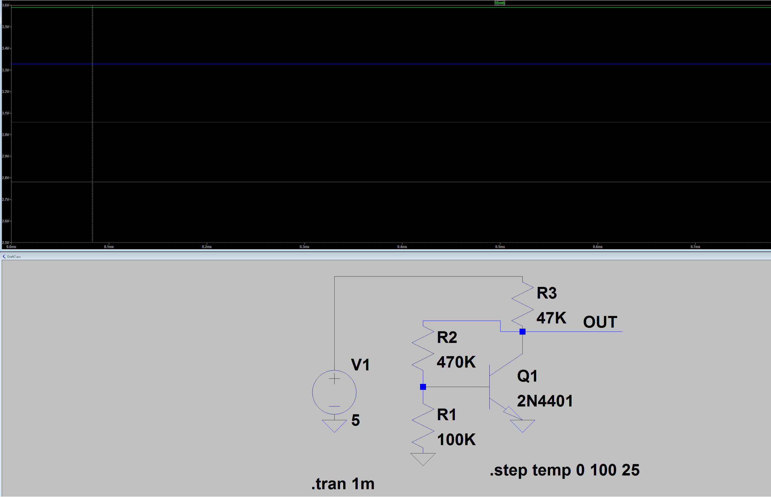
Edit: Here is a simulation result used as a simple Vbe multiplier.
0°C 3.591V
25°C 3.328V
50°C 3.057V
75°C 2.781V
100°C 2.500V
The current drops as the voltage increases (due to the use of a simple resistor as a current source) so the linearity isn't great= 11.2mV/K average at 0..25°C and 10.5mV/K average at 75..100°C, but for narrow excursions around room temperature it should be fine, or it can be corrected digitally. With a 10-bit ADC and 5V Vref the resolution is about 0.5°C, which is adequate for many purposes.
There are much better ways to measure temperature with a transistor, however the complexity is increased. Using matched transistors or multiple (2 or 3) currents with a single transistor allows cancellation of many of the transistor parameters that vary from unit to unit, as well as connection resistance. Unfortunately, the sensitivity is reduced by at least an order of magnitude so better analog circuitry is required.
Edit/Epilog:-
I tried this with a single diode-connected BJT (base connected to collector) with a 10K resistor to the regulated (and otherwise unused) 3.3V rail on an Arduino Nano. Reference set to nominal 1.1V as suggested by @EdgarBonet, summed 100 sequential readings.
Calibrated the voltage by adding a multiplier so the reading was accurate in mV compared to a handheld 3.5 digit DMM.
Wrote the equation for temperature based on the current room temperature and the mV, with an estimate of -2.0mV/K for the Vbe temperature coefficient.
Tested it at 0°C and 45°C against a type K bead thermocouple.
Adjusted the 2.0 to 2.2 to reduce the error at the temperature extremes.
adc *= 1.0532319391 * 0.01;  // calibrated voltage in millivolts, 100 summed
temp = -(adc - 556)/2.2 + 24.0;
Works quite well with only one unexpected thing- the INTERNAL1V1 constant was not defined even though the Arduino environment knows it is an ATMega328p (using an Arduino Nano). I added one line to code the definition:
#define INTERNAL1V1 2
analogReference(INTERNAL1V1);
-
2\$\begingroup\$ The sensitivity depends inversely on bias current. Lower bias current will give slightly higher sensitivity. And I am not sure but I think maybe a couple hundred microamps will give sensitivity of more like 1.8mV per degree. I think maybe 10uA is enough, but I guess it depends on the ADC leakage current spec. You want the bias current to be much higher than the ADC leakage current. \$\endgroup\$ Commented Oct 4, 2020 at 4:59
-
\$\begingroup\$ Note that you need an OP amp in order to read the signal using an Arduino (as the OP mentions in the main question). The Arduino required an impedance of 10kOhm or lower in order to stay within spec for the analog inputs \$\endgroup\$– FerrybigCommented Oct 4, 2020 at 15:31
-
\$\begingroup\$ @Ferrybig There are techniques for allowing several hundred K input impedance without significant error (10n cap + certain delays), or reduce the resistors 5:1 for similar results. \$\endgroup\$ Commented Oct 4, 2020 at 15:40
-
2\$\begingroup\$ Note that on most Arduinos you can set the voltage reference of the ADC to some internal reference lower than Vcc: 1.1V or 2.56V on AVR boards, 1.0V on the SAMD boards... \$\endgroup\$ Commented Oct 5, 2020 at 8:13
-
1\$\begingroup\$ At 1.1V a single diode-connected transistor with a 10K series resistor to +5 would work very nicely. Resolution about 0.5°C. Might have to average a bunch of readings. \$\endgroup\$ Commented Oct 5, 2020 at 8:24
Question
How can I use a 2N2222 transistor as a temperature sensor?
I'm supposed to use a TMP36 transistor for a class to read the temperature of the environment, but I only have a 2N2222 transistor; the Arduino will have an analog read of it, but the numbers won't change even if I heat it up. Am I screwed or can I fix this?
I am in high school studying for math.
Answer
Update 2020oct08hkt2248
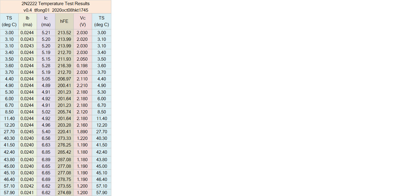
So I did the preliminary test and measured the three values, Ib (Note 1), Ic, and Vc against temperature from about 3°C to above 50°C (Note 2). I also use Excel to calculate β. A summary is given below.
Note 1 - The Ib column is almost constant, as is Vbe. So Vcc and Rb is an approximation of applying a current source to an diode (2N2222 BE junction), and measure Vbc, as advised by @Tony Stewart Sunnyskyguy EE75.
Note 2 - My cheapie digital thermometer for home use overflows somewhere above 50°C. The OP's requirement anyway is to measure the "environment" which I think is approx a range from 0°C to 50°C. So I won't bother for now to find a thermometer for higher temperature.
Actually my calibration plan is to use the DS18B20 temperature sensor to replace my cheapy home use thermometer.
Update 2020oct08hkt1413
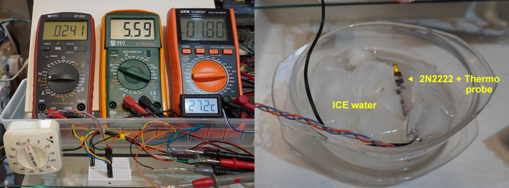
Now 2N2222 is enjoying a cold plunge
Update 2020oct08hkt1111
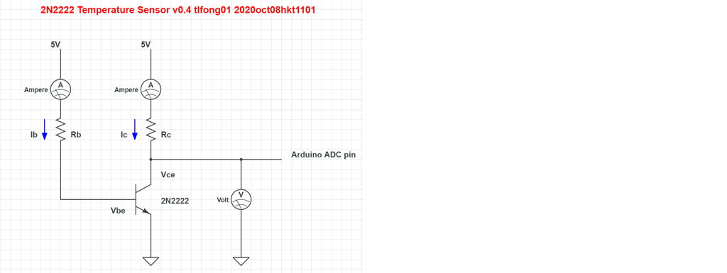
A more high school student friendly schematic of the 2N2222 temperature sensor.
Update 2020oct07hkt1549
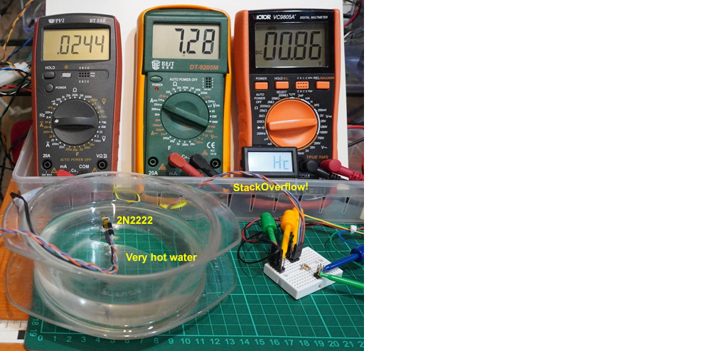
Sauna test results - stackOverflow!
Hot water bath overflows my digital thermometer!
Update - 2020oct07hkt1151
Tidying up messy wiring, getting ready for Hot Sauna Cold Plunge
Update 2020oct06hkt2141
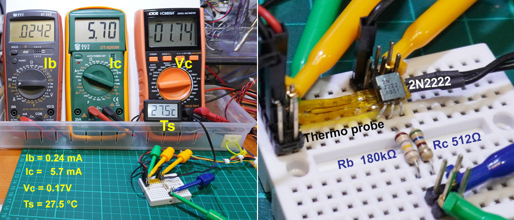
So I adjust the values of Rb and Rc to move operation region from saturation to amplification, where current gain is around 250, similar to the value measured by the multi-meter, as illustrated below.
I then used a hot gun to blow hot air to the 2N2222 circuit. I guess the temperature around the circuit should be higher than 50 degree C, because my hand could not bear it for more that one or two seconds.
I am glad to see that Vc, Ic, and Ib rose, as summarized below.
-------------------------------------------------------
  Temp      Ib (mA)     Ic (mA)      Vc (V)         β
-------------------------------------------------------
  28°C       0.0230         5.6        0.18       243
Hot air      0.0244         6.6        1.30       270
-------------------------------------------------------
Of course the temperature as measured by hand is very crude, but the changes of Ic, Vc, and β is significant.
I don't worry that Ic, Vc, and β vs temperature is non linear, because we can use software to calibrate, sort of flatten/straighten the non linear curve to a straight line.
Next step is to use ice cold water around 0°C and hot water at 90°C to measure and plot Ic, Ib, Vc, and β against temperature in C°.
Update 2020oct06hkt1534
Now I am updating my old design with an opAmp.
Update 2020oct0601
As I found that my old tests do not give expected results, because of wrongly chosen components values. So I am moving the old design and bad test results to the GiHub page.
I think @csabahu's answer is very good. So I am studying his design and using his testing parameters to do my coming tests. I originally thought that I should be using the 2N2222's current gain to amplify the very small output values for easy measurement. Now I thnik @csabahu's use of the opAmp is a much better approach, because the opAmp should not load down output signals and also can easily adjust gain factors.
But I have little experience in using opAmp for instrumentation. So I need to google some more tutorials before I start my new circuit.
My old design with Ic of the order 1mA has already saturated the 2N2222. Now I am thinking of up shifting the Ic test range from 1mA to 10mA, and even up to 100mA. My old selection of Ib of the order of 1uA is also too small for my cheapy multimeter to measure.
/ to continue, ...
References
(1) P2N2222A Amplifier Transistors NPN Silicon - On Semiconductor
Update 2020oct06
The old reference list was getting too long and messy, so I have moved those not too relevant old references (16 in total) to the GiHub page.
(18) Diode-Based Temperature Measurement - TI, Application Report SBOA277A–March 2018–Revised May 2019
(20) How do you get a temperature sensor from a transistor? - Randy Frank, Sensor Tips, 2017oct27
(22) AliExpress LM134/LM234/LM334 3-Terminal Adjustable Current Sources - TI, US $2/5pcs
Appendices
Update 2020oct06hkt1434
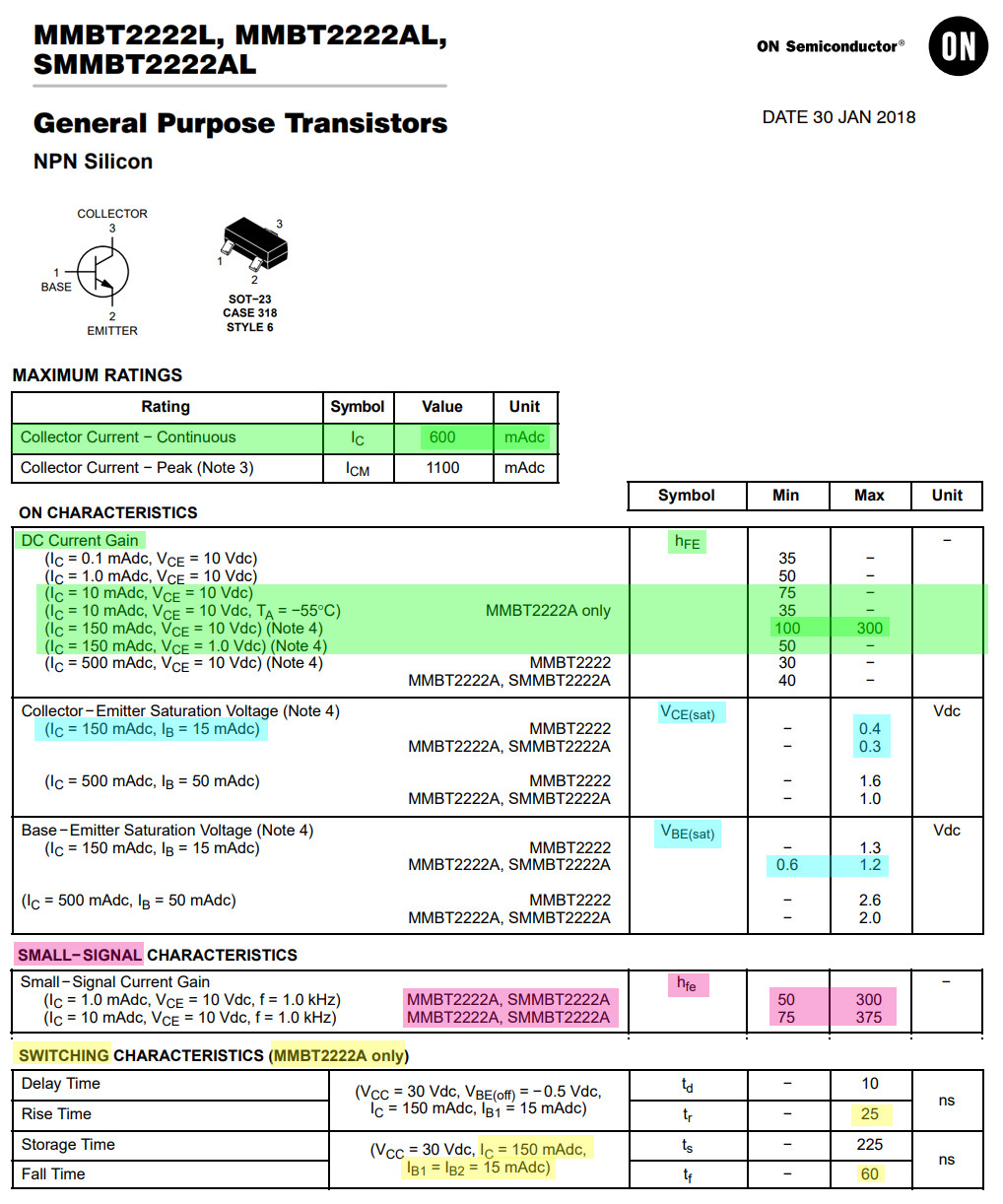
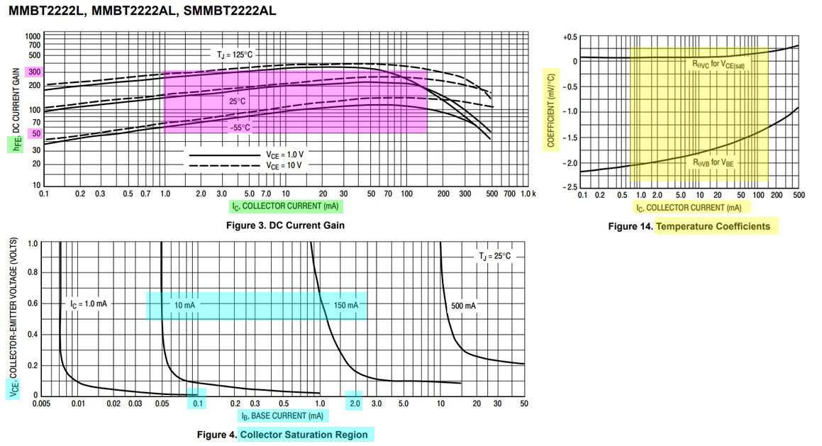
My first idea of testing plan is wrong, because I don't understand the small signal properties of 2N2222. My knowledge and experience is only on the use of 2N2222 as a switch. So I am studying the datasheet and thinking of designing a new test plan. One thing I am doing is to shift the Ib and Ic testing range, so it is easier to use my multi-meters to do measurements. The new datasheet summary is pasted below.
I am also using the new MMBT2222 datasheet instead of the old 2N2222.
-
6\$\begingroup\$ The dreadful P2N2222 is about to strike again. To the OP: watch out for inverted C and E terminals, if you have a 2N2222. \$\endgroup\$ Commented Oct 4, 2020 at 3:49
-
2\$\begingroup\$ @Sredni Vashtar, Many thanks for your very important and critical warning. Do you know why some chips have the two terminals inverted? In my long electronics hobbyist life, I have never heard of such a ridiculously dangerous pinout trap, for newbies, ninjas, and even pros alike. \$\endgroup\$– tlfong01Commented Oct 4, 2020 at 8:36
-
3\$\begingroup\$ @tlfong01 Please keep your edits to a minimum and your answers a bit shorter, the answers are a bit long. Thanks \$\endgroup\$– Voltage Spike ♦Commented Oct 6, 2020 at 5:39
-
3\$\begingroup\$ When you combine a fairly accurate - 2.2mV/'C NTC characteristics of the Vbe with base-collector shorted and then use a common emitter with hFE changing with T you get an inaccurate temperature sensor. -1 \$\endgroup\$– D.A.S.Commented Oct 8, 2020 at 4:23
-
5\$\begingroup\$ I don't consider any of those YT's video's as expert design references \$\endgroup\$– D.A.S.Commented Oct 8, 2020 at 5:13
If there is an unnecessary operational amplifier in the drawer, a very nice signal can be output from the transistor.
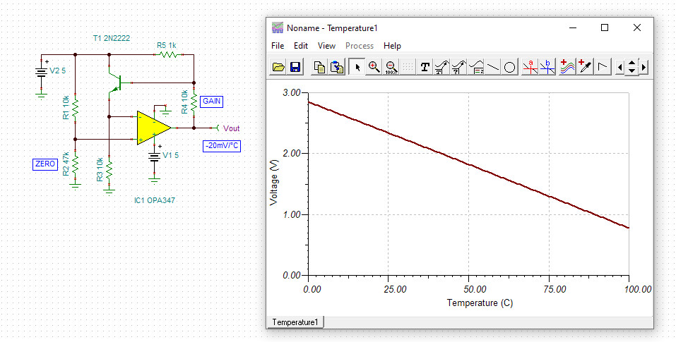
At zero degrees, set 3V at the output with a 47k resistor. Then at 100 degrees with 10k resistor to 1V. (Ice water or boiling water.)
Of course, if you only use it on your own machine, calibration can be purely with software.
-
1\$\begingroup\$ You probably meant to write 'potentiometer' instead of resistor. \$\endgroup\$ Commented Oct 5, 2020 at 18:03
-
1\$\begingroup\$ Almost. A smaller potentiometer with which the ratio of the given resistors can be fine-tuned. For example, a 2k potentiometer between 47k and 10k. Here, it is not the absolute value of the resistance that is interesting, but the voltage setting of the non-inverting input. Of course, this is only needed if we want to calibrate the thermometer. \$\endgroup\$– csabahuCommented Oct 5, 2020 at 18:38
-
1\$\begingroup\$ @csabahu, Ah, your colourful schematic is looking nice, and the opAmp Vout vs Temperature chart is impressively ideal. So I will search my jun bin for an opAmp and try it out. \$\endgroup\$– tlfong01Commented Oct 6, 2020 at 3:54
-
1\$\begingroup\$ @tlfong01, What's the weather like in your city today? Have you tried the thermometer? \$\endgroup\$– csabahuCommented Oct 6, 2020 at 19:31
-
1\$\begingroup\$ @csabahu, (1) Ah, I usually Yahoo to get the weather in my city: hk.news.yahoo.com/weather. (2) I do have a couple of thermometers. See update today (2020cot07) of my answer to see how I am using my digital thermometer. Cheers. \$\endgroup\$– tlfong01Commented Oct 7, 2020 at 4:26

