2
\$\begingroup\$

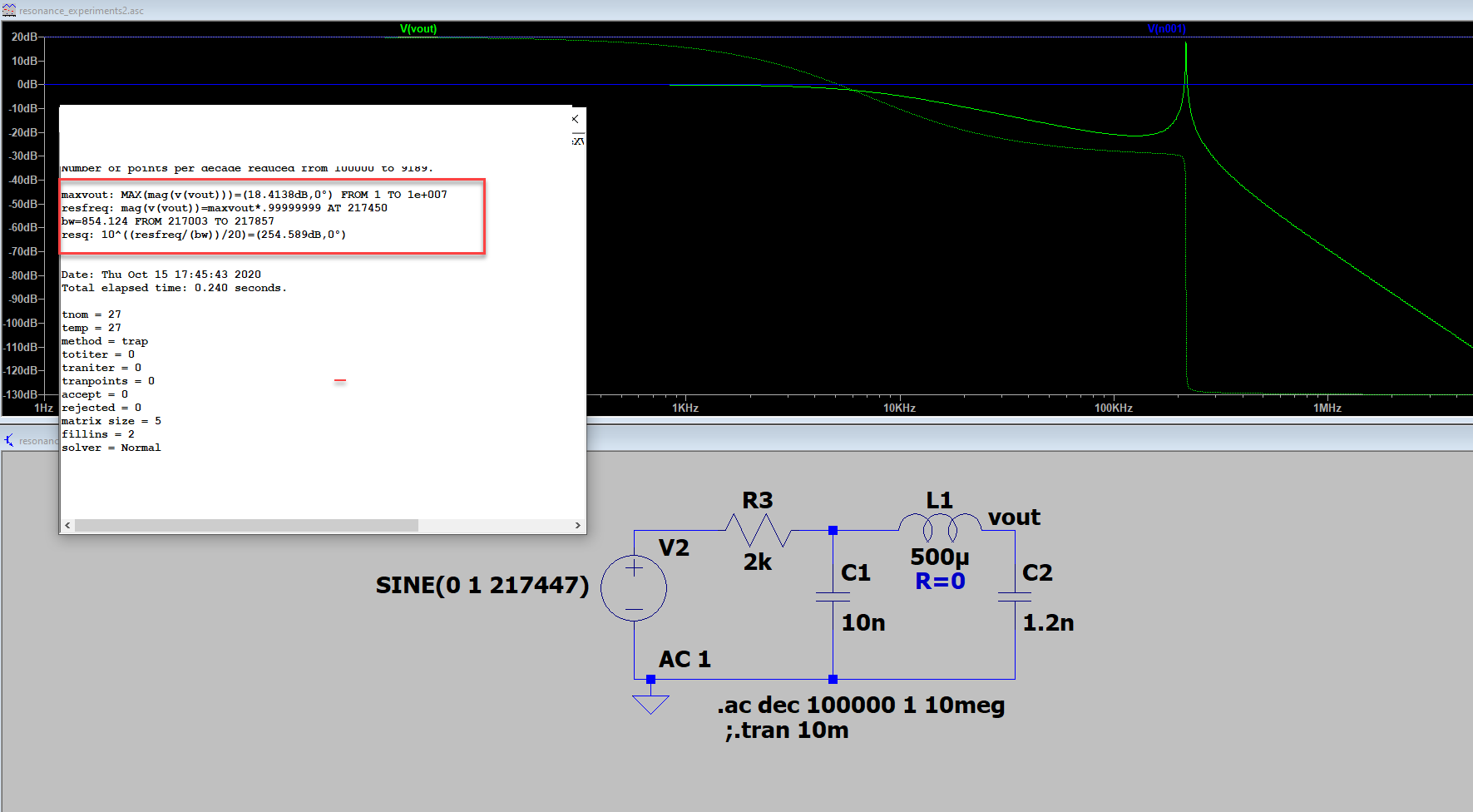
I have a simple circuit pi circuit. When I do the math and subsequently run the simulation on LTSpice, I get a similar answer - the resonance occurs at f= 217447Hz (math), 217450(LSpice).

enter image description here

The error log shows the following measurements:

.meas AC maxVout MAX mag(V(vout))
.meas AC resFreq when mag(V(vout))=maxVout*.99999999
.meas AC BW TRIG mag(V(vout))=maxVout/sqrt(2) RISE=1 TARG mag(V(vout))=maxVout/sqrt(2) FALL=last
.meas AC resQ PARAM 10^((resfreq/(bw))/20)    **this result is in decimal, but displays as dB in the error log file.

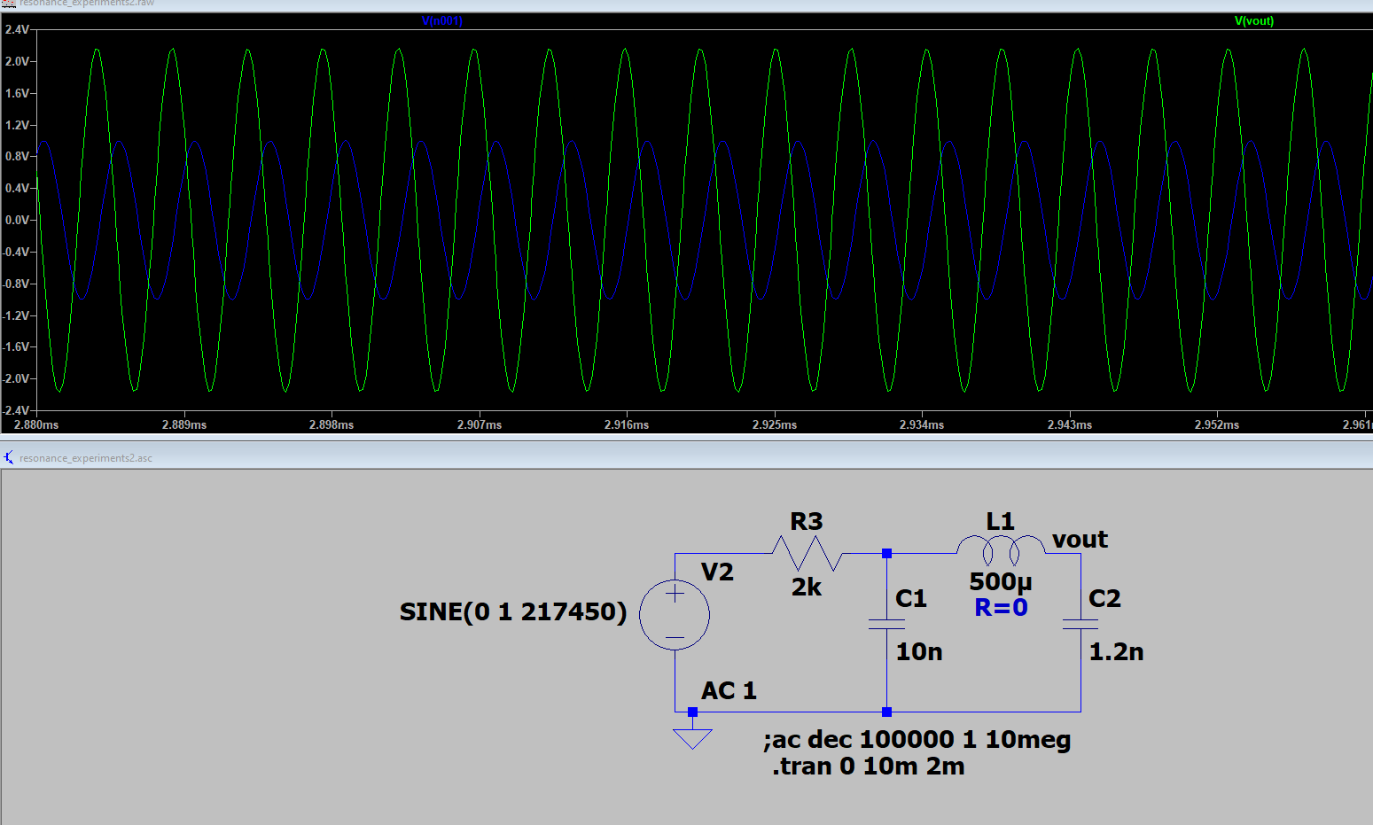
When I run a transient analysis, with the voltage source set up as sine wave as $$ 1\cdot Sin(2\cdot\pi\cdot 217450\cdot t)$$, my expectation is the that output at node vout would be around 8.33V (10^(18.4138/20)volts). However, the output of the transient response, the maximum amplitude of vout is around 2.1V volts:

enter image description here

What's going on? Has anyone else run into something like this?

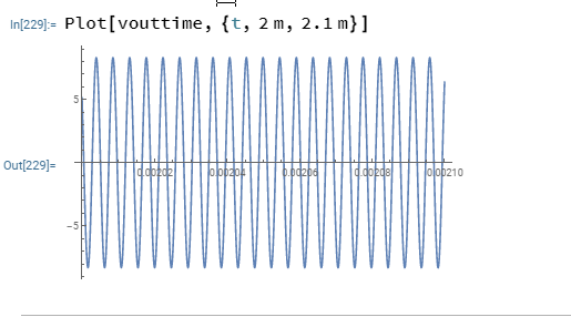
To check, I used Mathematica to plot the time domain output of my circuit's transfer function (convolved with the input sine wave source -ie, set Vin in my transfer function as a sine wave of frequency 217450 in the laplace domain, and then took the inverse laplace), I get something like I'd expect:

enter image description here

I don't know why LTSpice is not giving me the same answer ---I must be doing something wrong.

\$\endgroup\$
2
  • 1
    \$\begingroup\$ +1 for doubting yourself and your usage of the tool, instead of blaming the tool. \$\endgroup\$ Commented Oct 16, 2020 at 8:25
  • \$\begingroup\$ I always hesitate to blame the tool....;-) \$\endgroup\$
    – jrive
    Commented Oct 19, 2020 at 3:44

1 Answer 1

3
\$\begingroup\$

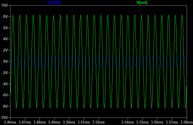
When in doubt, if a transient simulation isn't giving expected results, decrease the maximum time step.

I was able to reproduce your results with the default settings.

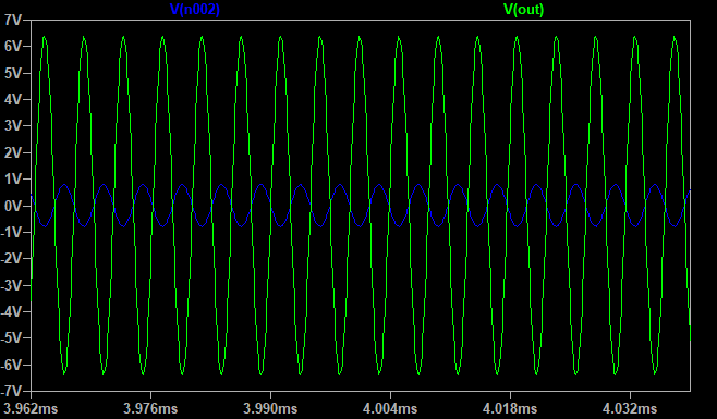
But when I set the maximum time step to 0.1 us, I get much closer to the expected results:

enter image description here

(n002 is the voltage source output terminal)

When I reduce the maximum timestep to 0.02 us I get very close to the theoretical amplitude:

enter image description here

\$\endgroup\$
3
  • \$\begingroup\$ piece of cake! thank you for your quick response.....this was driving me nuts!! \$\endgroup\$
    – jrive
    Commented Oct 15, 2020 at 23:30
  • \$\begingroup\$ Seems that larger timestep lowers the resonant frequency slightly. With default timestep I got 8.3V at 215900 Hz. \$\endgroup\$ Commented Oct 16, 2020 at 5:40
  • 2
    \$\begingroup\$ @jrive The main reason behind this is due to the very high quality factor (you have no load). That means high derivatives of the slopes which, in turn, mean that the \$\text{e}^{-b_1t},\,b_1\rightarrow 0\$ term takes a lot to converge. If you had used a lower Q, smaller timesteps would have not been necessary. \$\endgroup\$ Commented Oct 17, 2020 at 8:37

Your Answer

By clicking “Post Your Answer”, you agree to our terms of service and acknowledge you have read our privacy policy.

Not the answer you're looking for? Browse other questions tagged or ask your own question.