1
\$\begingroup\$

schematic

simulate this circuit – Schematic created using CircuitLab

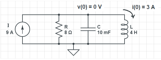
I already did my own solution but I just want to check if I got everything right, especially in determining the initial conditions. Here is my own understanding:

So, for t<0, the current source and capacitor is an open circuit and the inductor will be a short circuit. Hence, all the current will flow to the short circuited inductor. $$ t<0: $$ $$ i(0) = 3A; $$ $$ v(0) = 30; $$ $$ \frac{di (0)}{dt} = \frac{30}{4} = 7.5 $$

Now, at t > 0: We could do source transformation with the 30V source and 10 ohm resistor, hence, everything will be in parallel. I combined the 6 A and the 3 A to get 9 A current source and combined the two resistances to get:

$$ t>0: $$ $$ i(0^+) = 9A; $$ $$ R = 10||40 = 8; $$ $$ resonant freq. = \frac{1}{√LC} = 5 = 7.5 $$ $$ α = \frac{1}{2RC} = 6.25 $$ $$ s_1 = -2.5, s_2 = -10 $$ Here we can see that we will have an overdamped response hence our solution would be of the form: $$ i(t) = I_f + A_1e^{-2.5t} + A_2e^{-10t} $$

To get A1: $$ i(0) = I_f + A_1 + A2 $$ $$ 3 = 9 + A_1 + A_2 $$ $$ -6 - A_2 = A_1 $$

To get A2: $$ \frac{di (0)}{dt} = \frac{30}{4} = 7.5 = -2.5A_1 + -10A_2 $$ $$ 7.5 = -2.5(-6-A_2) - 10A_2 $$ $$ A_2 = 1 $$ $$ A_1 = -7 $$

So my final equation would be: $$ i(t) = 9 -7e^{-2.5t} + e^{-10t} $$

Did I do everything right? I feel like my initial conditions analysis is wrong but when I checked using LTspice, im getting the current inductor to be almost 3A for t<0 and 9A for t>0. But when I check for voltage on the node of Vc, im getting 3mV which I don't understand.

\$\endgroup\$

1 Answer 1

0
\$\begingroup\$

I'll present here the theoretical solution. For \$- \infty < t < 0\$ only the voltage source is present in this RLC parallel circuit, which establishes an initial inductor current of \$i(0-)=i(0+)= 30 \space V / 10 \space \Omega = 3 \space A\$. Note also that \$v(0-)=v(0+)= 0 \space V\$, since the inductor can be seen as a short circuit for \$t < 0\$. So, the circuit can be converted as shown on figure below:

RLC series converted

Applying KCL on upper node:

$$ -I + \frac{v(t)}{R} + C\frac{d}{dt}v(t) + i(t) = 0 $$

Replacing \$v(t) = L\frac{d}{dt}i(t)\$

$$ LC\frac{d^2}{dt^2}i(t) + \frac{L}{R}\frac{d}{dt}i(t) + i(t) = I $$

The characteristic polynomial is:

$$ LCs^2 + \frac{L}{R}s + 1 = 0 $$

With roots

$$ s_{1,2} = -\frac{1}{2RC} \space \pm \sqrt{\left ( \frac{1}{2RC}\right )^2 - \frac{1}{LC}} $$

As \$\left ( \frac{1}{2RC}\right )^2 > \frac{1}{LC}\$, the system is overdamped, with two real and distinct roots \$s_1 = -2.5\$ and \$s_2 = -10\$ for the current case.

The complete response has the form

$$ i(t) = i_f + A_1e^{-s_1t} + A_2e^{-s_2t} $$

where \$i_f\$ is the forced response (in this case, \$9 \space A\$). The constants \$A_1\$ and \$A_2\$ can be determined from the initial conditions.

$$ \left\{\begin{matrix} i(0) = I + A1 + A2 & (1)\\ \frac{d}{dt}i(0) = -s_1A_1 -s_2A_2 & (2)\\ \end{matrix}\right. $$

Note that \$v(0) = L\frac{d}{dt}i(0)\$. As \$v(0) = 0 \space V\$ then, \$\frac{d}{dt}i(0) = 0 \space A/s\$ Therefore

$$ \left\{\begin{matrix} 3 = 9 + A1 + A2 & (1)\\ 0 = -2.5A_1 -10A_2 & (2)\\ \end{matrix}\right. $$

Resolving, \$A_1 = -8\$ e \$A_2 = 2\$

Finally, the inductor current in Ampere is

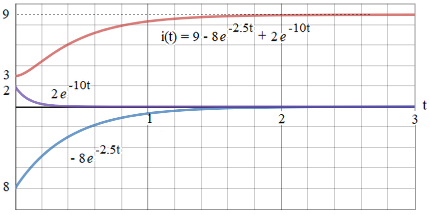
$$ i(t) = 9 -8e^{-2.5t} + 2e^{-10t}$$

With graph

Graph RLC series

\$\endgroup\$
1
  • \$\begingroup\$ I have since edited my sol. since I posted this question a few days ago and I have the same answer as you! I got confused by my i(0) that's why my A1 and A2 was wrong on my first solution. \$\endgroup\$
    – user263783
    Commented Oct 19, 2020 at 12:48

Your Answer

By clicking “Post Your Answer”, you agree to our terms of service and acknowledge you have read our privacy policy.