1
\$\begingroup\$

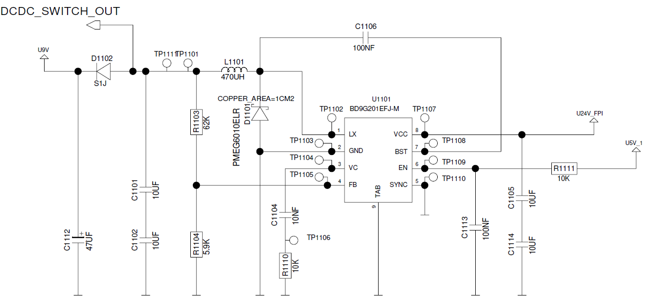
I am using this buck converter.

Schematic:

enter image description here

Buck Converter Specifications :

  • Input Voltage - 18V to 32V
  • Switching Frequency - 300kHz
  • Output Voltage 9V
  • Load Current - 0mA to 200mA Maximum.

When measuring the switching frequency using an oscilloscope, I am placing the probe directly on the TP1102 and also measuring the output voltage on the 47uF capacitor pad.

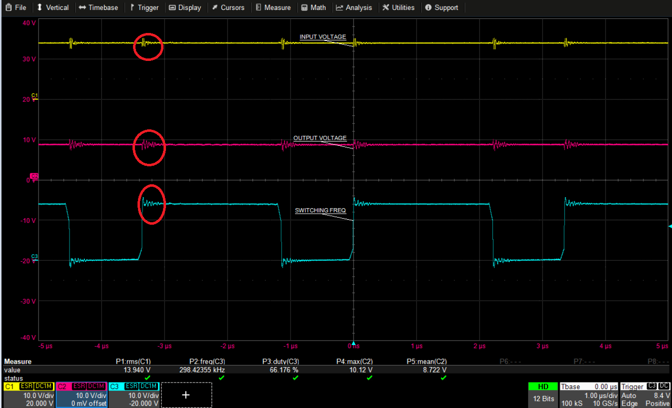
I got the below waveforms :

Input voltage of 14V:

enter image description here

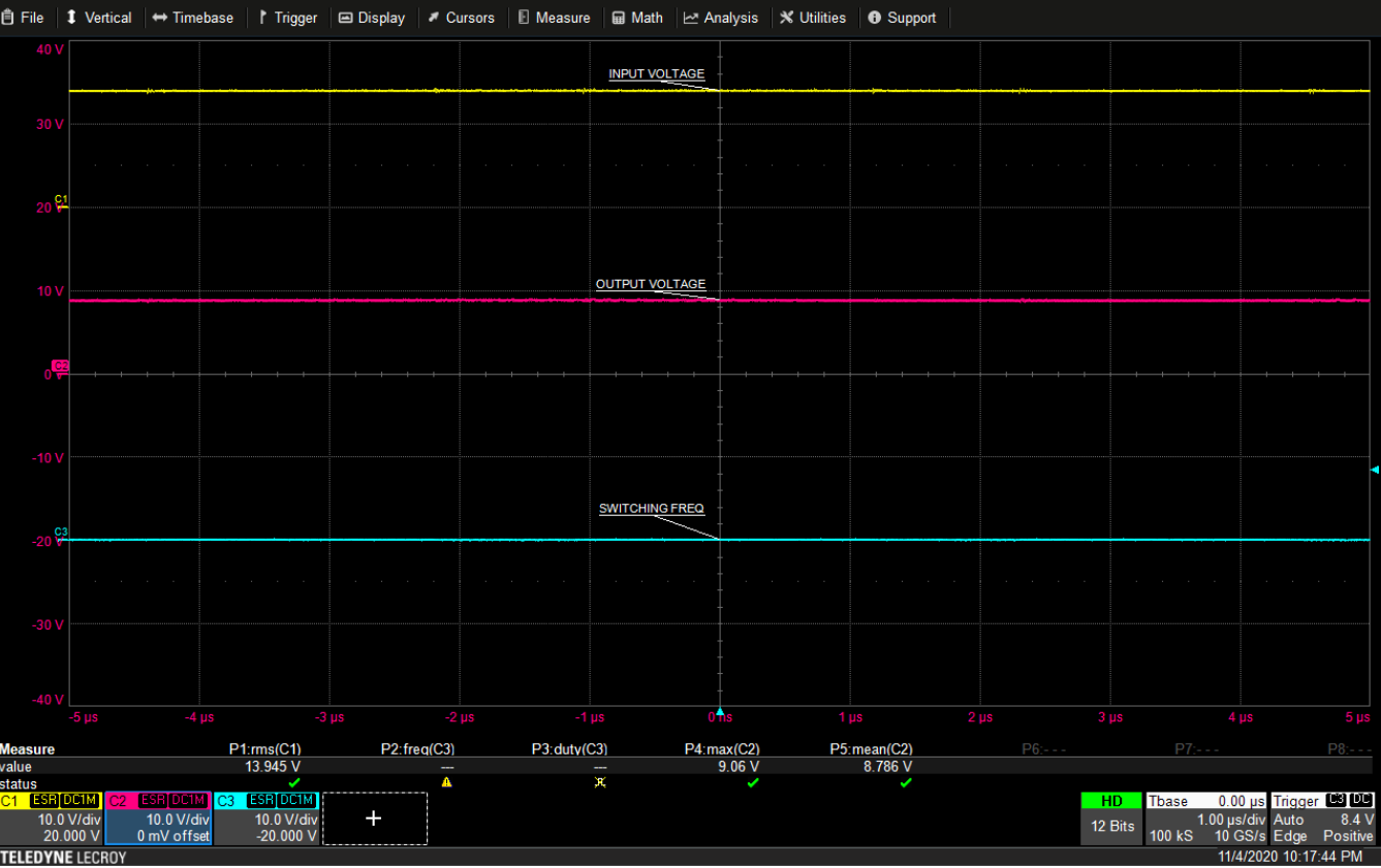
However, with the same input voltage, I am just removing the probe which was placed at the switching frequency node. Now, I didn't observe the ringing.

Input voltage of 14V without probing the switching frequency :

enter image description here

As you can see, the ringing vanished once I disconnected the probe.

Can someone tell me how this ringing at the switching frequency node is happening even though I am probing at the TP1102 and how this is coupling at the other probes also?

Please also provide a solution on how to avoid this ringing while measuring the values.

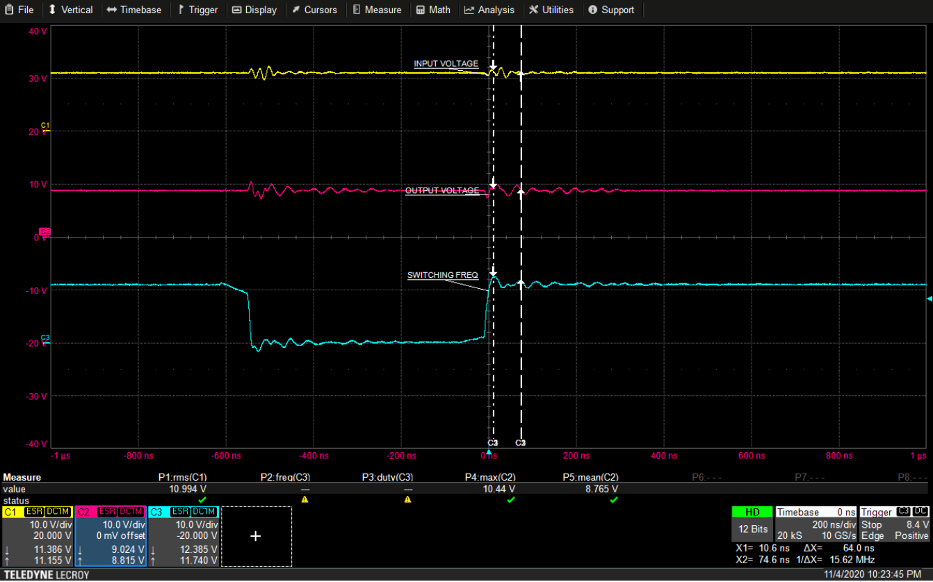
Below is the ringing frequency:

enter image description here

\$\endgroup\$
2
  • \$\begingroup\$ How the probe grounds are connected? \$\endgroup\$
    – Justme
    Commented Nov 5, 2020 at 5:48
  • \$\begingroup\$ I have connected only one probe ground clip (not the short spring type ground) on a ground terminal present in the board. \$\endgroup\$
    – user220456
    Commented Nov 5, 2020 at 6:15

2 Answers 2

0
\$\begingroup\$

Your probing technique is the cause, three mistakes already.

Use ground on both probes, not just one.

Don't connect to a ground test point far away.

Don't use ground clip, use the spring. Wire of the clip is too long to provide meaningful high frequency results.

\$\endgroup\$
4
  • \$\begingroup\$ Thank you for the answer. But how is the ringing coupled to other oscilloscope probe channels as well? Please let me know on how to avoid. And how can I use spring type ground on all 3 probes? It will be difficult right? \$\endgroup\$
    – user220456
    Commented Nov 5, 2020 at 9:00
  • \$\begingroup\$ Because you have connected the scope with an inductance, during the edge, there is a voltage difference between scope and board. All channels have same voltage difference then. And if you have not designed the prototype with enough features to allow easy probing and testing of things you want to test, then yes, testing might be difficult. \$\endgroup\$
    – Justme
    Commented Nov 5, 2020 at 9:16
  • \$\begingroup\$ Sorry to ask multiple questions. Could you please tell me how there is a voltage difference between the scope and board? What would be voltage on the scope and on the board during the edge? And how will all the channels have the same voltage difference? Sorry to ask. Could you please explain in simple terms. \$\endgroup\$
    – user220456
    Commented Nov 5, 2020 at 9:24
  • 1
    \$\begingroup\$ Scope leads have inductance. Thus you have connected PCB ground to scope ground with an inductor. Inductance does not allow high frequencies to pass, and will pass low frequencies only. Edge has high frequencies, so the grounds do not stay at same potential over the inductance during a fast edge. \$\endgroup\$
    – Justme
    Commented Nov 5, 2020 at 9:42
0
\$\begingroup\$

A typical 10:1 probe with 6" long Ground lead will resonate near 150MHz.

The inductance of 1nanoHenry per millimeter (or 25 nanoHnry/inch, or 150 nanoHenry total), and the 10 /12/15 pF probe capacitance are your circulating path.

\$\endgroup\$