0
\$\begingroup\$

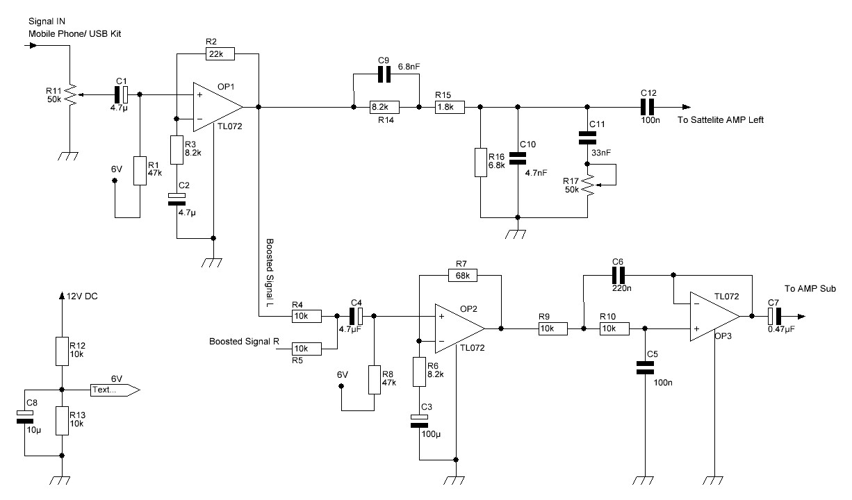
I built a 2.1 subwoofer circuit. The schematic is below. The problem is the sound is low volume. It should be louder than this. I want to confirm the coupling capacitor values are ok in every stage.

The main chip amplifier is TDA7377. It is configured as a stereo bridge.

Note: The diagram shows only a single channel & a subwoofer filter.

enter image description here

\$\endgroup\$
7
  • 1
    \$\begingroup\$ What's the input impedance of the stage following your preamp (the one marked "To AMP Sub")? If it's low enough, C7 could be your problem. \$\endgroup\$
    – TimWescott
    Commented Nov 5, 2020 at 17:18
  • 1
    \$\begingroup\$ And is the gain just too low overall, or is it a frequency-dependent thing? \$\endgroup\$
    – TimWescott
    Commented Nov 5, 2020 at 17:18
  • \$\begingroup\$ Thanks.The datasheet of TDA7377 shows 15Kohms input impedance in bridge mode. (sub out following). And 30Kohms single ended ( sattelites following). \$\endgroup\$
    – Joseph143
    Commented Nov 5, 2020 at 17:36
  • \$\begingroup\$ Why don't you simulate it. Saying the output is low means nothing. \$\endgroup\$
    – Andy aka
    Commented Nov 5, 2020 at 18:01
  • 1
    \$\begingroup\$ The circuit looks fine for the TDA7377, but that output amplifier may be to wimpy. In bridge mode, the TDA7377 can only supply a 15W or so into a 4-ohm load with a 12V supply. Not much for a subwoofer. \$\endgroup\$ Commented Nov 5, 2020 at 20:08

2 Answers 2

1
\$\begingroup\$

Considering it takes me 15 minutes to simulate your analog Bode plot with experience, you ought to learn to define a problem with design specs vs results and simulate with your fave tool.

I like www.Falstad.com/afilter.

You can change values on the fly with a mouseover & wheel or rt. click > edit. As @TimWescott said in comments, your 100n C12 is far too small if using Bridge input 10k min Rin.

Also, Tone control Pot is too sensitive at 50k and a few other improvements can be made after you define your tolerance on specs.

Even if it takes 1/2 hr, why not simulate it before hand?

Nice looking schematic BTW.

\$\endgroup\$
0
\$\begingroup\$

Your filters for the satellite speakers reduce their levels.
The amplifying opamp OP2 for the subwoofer increases its level almost 9 times. Amplify the satellite signals instead of reducing them.

The subwoofer filter cuts high frequencies above 110Hz, will the satellites go down that low?
Increase the lowpass filter cutoff frequency to 200Hz or 300Hz.

Phase shift between the satellite filter and the subwoofer filter might be causing a notch filter reduction at the crossover frequency.
Use a Linkwitz-Riley crossover for both highs and lows that does not produce a phase notch.

\$\endgroup\$

Your Answer

By clicking “Post Your Answer”, you agree to our terms of service and acknowledge you have read our privacy policy.

Not the answer you're looking for? Browse other questions tagged or ask your own question.