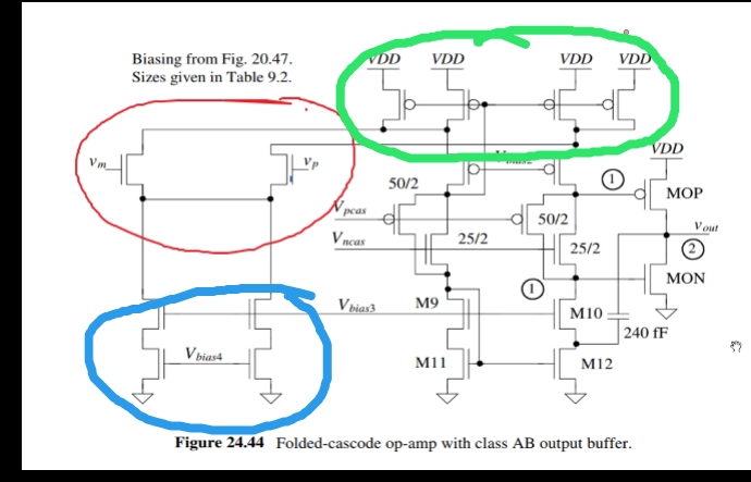
Good day to all. I'm doing a self study about the circuit shown above. I kind of don't understand which structure biases the differential pair(red). The explanation I read from the book that it is the structure in green that biases it, but the lecture I'm following says it it's the structure in blue that biases the diff pair. Which one is true? Please bear with me my command of english language is not that good. Thank you.
1 Answer
From what I see in your schematic, all the BIAS VOLTAGES are magically provided by external MAGIC bias generation (a stack of FETs).
The upper 4 FETs are a pullup current, subtracting from the diffpair current.
The residual, after subtraction, descends into the voltage_gain section below.
Regarding the bottom left 4 FETs: these are externally biased; the upper two are cascade shields, to stiffen the current sources FETs below, improving common mode rejection.

