1
\$\begingroup\$

I'm going to convert my DeWalt charger from 110V to 240V as I got sick of lugging a step converter around.

I have found two guides which use the exact model of charger I have but they have partly different solution. I would like to know more of what could be the reason that they did what they did.

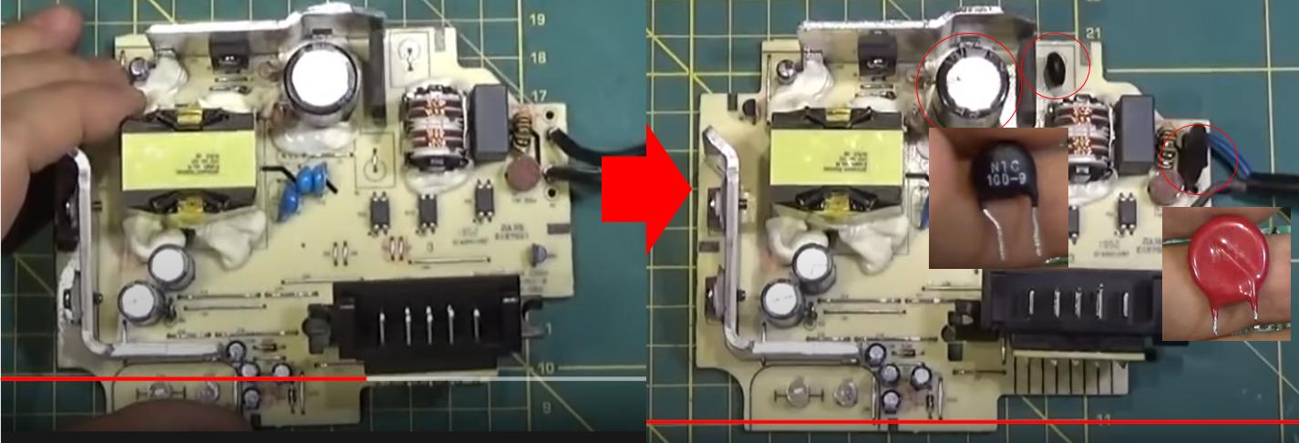
It is clear that the transformer that powers the charging circuit can handle 240V. Both of the guides replaced the 200V 220uF which I totally understand - that capacitor would pop under 240 VAC and should be replaced with a value above the peak 400V + should be fine.

Now the similarities end, the first guide changed the capacitor and added 2 0.33Ohm 5W resistors.

enter image description here

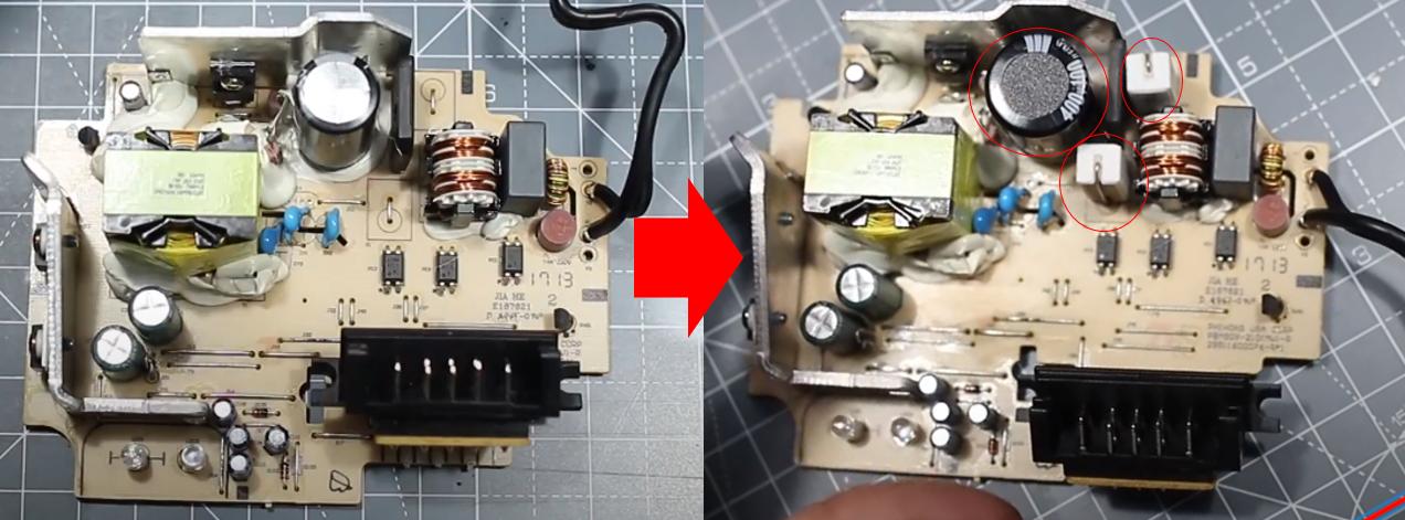
The second guide did not speak in english so I did not understand what he was saying but basically I think he add a varistor on the main input and instead of using a resistor I'm not sure what that black thing is (ceramic capacitor?) but why would he add a capacitor? If you closely look on either of the videos you might notice that that slot is labeled "R" so I assume a resistor is supposed to be placed there (instead of a jumper.)

enter image description here

Can someone help explain to me what could they possibly be doing? Sadly I don't currently have my charger so I can't take more detailed pictures of the circuit. But maybe someone may have an idea based on past experience.

\$\endgroup\$
20
  • 1
    \$\begingroup\$ It would be significantly more time and cost effective to purchase a compatible adapter locally even if it is not brand name. you risk breaking your only charger permanently, despite the inconvenience your current system works, rework has non zero probability of failure \$\endgroup\$
    – crasic
    Commented Nov 10, 2020 at 16:28
  • \$\begingroup\$ The resistors limit inrush current to the input cap(s). The black disk is most likely a PTC thermistor or polyfuse type of device. It functions similar to the resistors, but is intended to have lower loses, as its resistance is lower when cool, but increases when hot, which happens during high currents like during inrush. \$\endgroup\$
    – Aaron
    Commented Nov 10, 2020 at 17:13
  • 1
    \$\begingroup\$ @crasic no worries i have 3 of them, at first ill do 1, observe for 1 or 2 months, if its still good then ill be converting the others \$\endgroup\$
    – Jake quin
    Commented Nov 10, 2020 at 17:14
  • 1
    \$\begingroup\$ @crasic That's up to the asker to decide \$\endgroup\$ Commented Nov 10, 2020 at 17:15
  • 2
    \$\begingroup\$ It is quite risky to do this without having an idea of electrical margins on all the components. Usually, the main MOSFET is rated for 500 V in a single mains input like a 110 V version which translates in a 155-V bus (200-V capacitors). Go to 230 V rms and you end-up having 330 V across these capacitors (400 V types are necessary). The MOSFET needs to be a 600/650-V type. Then, the output diodes may not survive the extra stress as the voltage at the anode will swing more negative than before. Finally, the peak current in the transformer may be much higher considering the possible overshoot. \$\endgroup\$ Commented Nov 10, 2020 at 17:44

1 Answer 1

1
\$\begingroup\$

It's all in the comments already. A risky business and can cause bigger damage than you expect. Think about a fire when you are sleeping. Without a schematic and proper research its detailed operation it's impossible to decide how near to blow the charger really is after making those changes.

I have seen chargers that operate as well with 110V and 240V and both 50 and 60Hz. They are designed for that range. Larger margins require more complex design and higher cost parts. It's very difficult to believe that mass produced equipment suppliers want to carry that extra cost overburden.

Where I live modifications like this would be considered criminal, because there still reads all original supplier's texts and the device is changed to other. In addition only a contractor who has the licence determined by the regulation code can legally make works which change the structure of mains AC operated equipment.

Not asked: The white glue mass is essential to keep the device at least some time as one piece when it's transported in a toolbox in a car. Soldering joints alone will not stand vibrations of big parts. The ceramic resistors need it as well as the capacitor.

\$\endgroup\$
3
  • \$\begingroup\$ I do thank every one for giving their opinions, i have since abandoned of doing this, because as you said the risk is not worth it. I mean there are 240v version available of the chargers, its just US marketing saying its 20v "max" battery and really just have the same number of battery (5) on the 18v counterpart. the 18v battery will also reach 20v on a full charge. \$\endgroup\$
    – Jake quin
    Commented Dec 30, 2020 at 17:44
  • \$\begingroup\$ That is just another comment, it's not an answer. As long as you don't show any partical advice on to convert the device to 220v as the author asked, you do not belong this section. You can easily fit the comments and if it's important enough you'll get enough likes to get attention \$\endgroup\$ Commented Feb 20, 2021 at 8:35
  • \$\begingroup\$ The questioner seemed to ask how rational the presented modificationa are. Clicking the green checkmark was possible to be undone if it was an accident. \$\endgroup\$
    – user136077
    Commented Feb 20, 2021 at 10:37

Your Answer

By clicking “Post Your Answer”, you agree to our terms of service and acknowledge you have read our privacy policy.

Not the answer you're looking for? Browse other questions tagged or ask your own question.