0
\$\begingroup\$

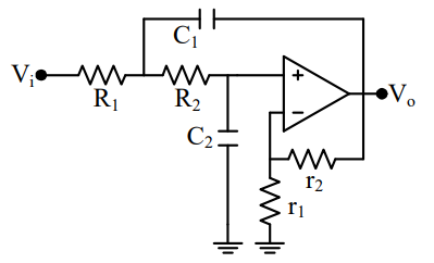
I am considering the following lowpass Sallen & Key filter:

enter image description here

My components are the following

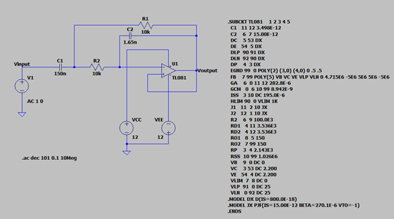
  • \$R_1=10 k\Omega\$
  • \$R_2=10 k\Omega\$
  • \$C_1=150 nF\$
  • \$C_2=1.65 nF\$

Now I have performed a complementary transformation to obtain a Bandpass filter. Here is the schematic on LTSpice

enter image description here

Now, when I simulate this circuit I get a very odd response: enter image description here
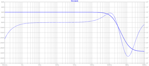
It doesn't look at all like a bandpass filter. It looks like a low pass one, but I know that is because of the OPAMP own frequency response. What went wrong with my simulation, why is this happening?

\$\endgroup\$

2 Answers 2

1
\$\begingroup\$

Solved: When applying the complementary transformation I forgot to swap my infinity resistance r1 and my zero resistance r2. The positive terminal of the OPAMP should be connected to ground.

\$\endgroup\$
1
  • 1
    \$\begingroup\$ Correct - now you have a bandpass circuit using the multi-feedback topology. The opamp is assumed to have an infinite gain. \$\endgroup\$
    – LvW
    Commented Nov 13, 2020 at 10:16
1
\$\begingroup\$

You have positive feedback in your circuit. The output is latched high. The reason for the fall off at higher frequencies is the internal behaviour of the op-amp as you've mentioned.

\$\endgroup\$

Your Answer

By clicking “Post Your Answer”, you agree to our terms of service and acknowledge you have read our privacy policy.

Not the answer you're looking for? Browse other questions tagged or ask your own question.