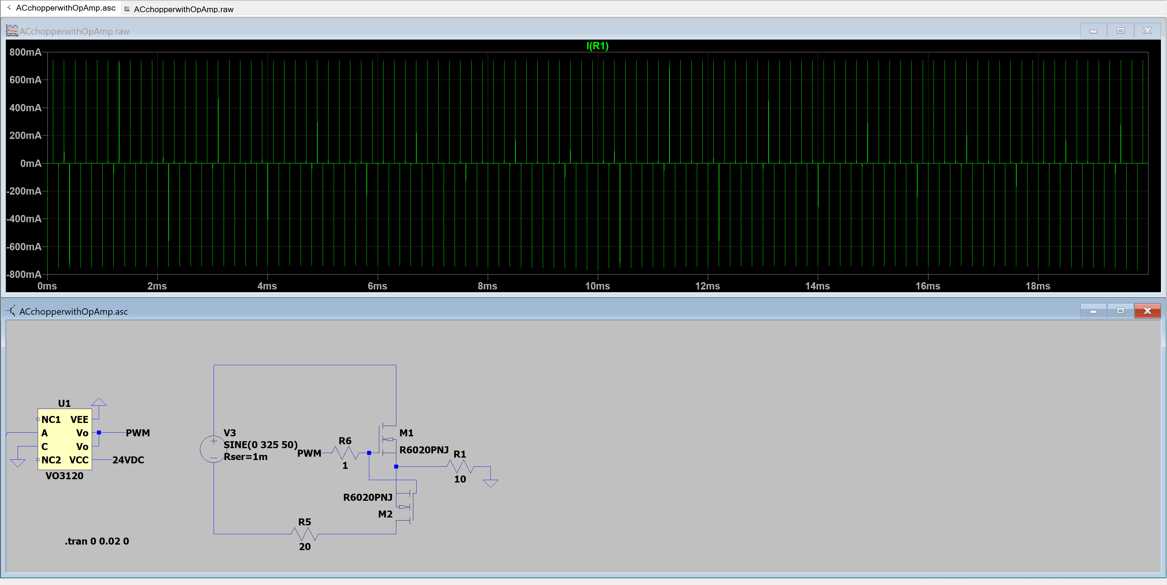
I have a circuit with 2 anti parallel mosfets driven from a gate driver IC. I understand how mosfet gate charging works. A big gulp of current is necessary to switch the mosfet fast. After that gate current is as good as zero(except the leakage current). But when discharging the mosfet i see a current flowing into the source. What is the reason for this? I thought the mosfet would also discharge via the gate( as the mosfet driver IC has a push pull configuration. Can anybody explain me what's going on?
1 Answer
\$\begingroup\$
\$\endgroup\$
1
Capacitors have two terminals. When charging it with current, current flows on both terminals. Same happens here. Basically, you can think that the FET gate and source are the terminals of the gate capacitance, so the current flows in these terminals. Actually the gate has capacitance to both source and drain, and the Ciss parameter in datasheet is the total gate capacitance.
-
\$\begingroup\$ Thank you for your advice. Seems logic. I thought the gate an source/drain had a very high resistance between them. So there couldn't be any current flow between gate and source or drain. Except when it's in transition mode apparently. \$\endgroup\$ Commented Nov 16, 2020 at 23:11

