3
\$\begingroup\$

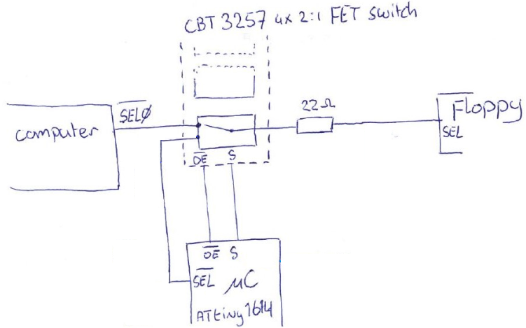
I am trying to hack some signals coming from an old computer going to a Floppy drive using an ATtiny1614 microcontroller. Normally the computer has full control of the signal lines but at some window in time, the computer is decoupled and MCU takes over. enter image description here
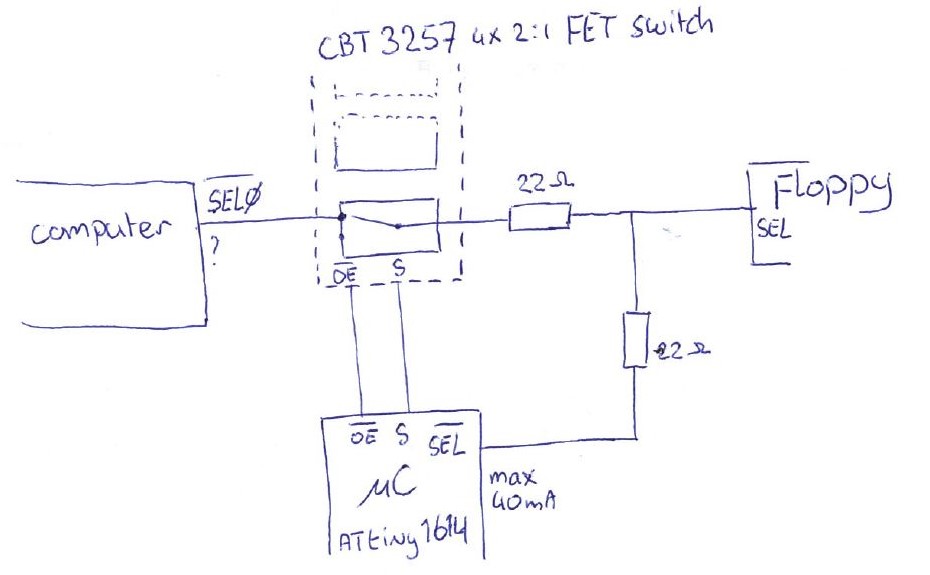
The signal lines (I am using 4, but for simplicity I have drawn only one) are cut off using a CBT3257 FET 4x 2:1 (de)multiplexer as not to disrupt the original timings, since it's high speed. Switching is controlled by the MCU pulling the output-enable (_OE) on the switch high which turns the switch output to high impedance, then making the SEL pin on the MCU an output.

  • Vcc is 5V TTL everywhere
  • No info on the current the computer can sink or source, or on the Floppy
  • ATtiny can sink/source 45mA max per pin
  • I cannot use the secondary input pins of the switch on 2 of the 4 ports since I am using those to switch 2 select lines around.

problem

If there is a bug in the MCU software it can occur that both the switch and MCU outputs are enabled, which then can short.

What can I do to protect the circuit in case I mess up the software?

Preferably using fairly inexpensive components, and not too many. I would like to avoid another IC.

what I've tried

  • I need about 122 Ohm to limit 5.5V TTL to limit the sink/source current of the ATtiny's pins to a a safe 45mA. This can be implemented by putting down two 68 Ohm resistors on the line. The Floppy, however, fails to respond properly using anything much above 22 Ohm (as per the picture). Wether this is because the signal gets too weak, voltages out of spec or some timing issue maybe due to a capacitive effect I don't know.
  • replacing the CBT with a 74LS257, which has proper TTL output, to boost the output and enable me to maybe use a higher resistor on the line, but this resulted in timing errors.
  • AND-ing the lines from the switch and the MCU using diodes and pull-up resistor, but this also caused the computer-floppy communication to fail.

I have access to an 8 port logic analyser with digital (I assume CMOS level) inputs and an analog Scope (so no memory).

Any ideas? Thanks

\$\endgroup\$
5
  • \$\begingroup\$ Which computer? Which floppy interface? Which floppy drive? What pins on the interface? \$\endgroup\$
    – Justme
    Commented Nov 20, 2020 at 14:55
  • \$\begingroup\$ Amiga 500; have no info on its floppy controller. Floppy is Chinon F354E, on which I also have no datasheet and besides other Amigas may/will have other drives. As for the interface pins: old.pinouts.ru/HD/InternalDisk_pinout.shtml though not really relevant I think. \$\endgroup\$
    – durandal
    Commented Nov 20, 2020 at 15:07
  • \$\begingroup\$ Random trivia: there are actually analog storage oscilloscopes that have analog memory! They are in every way I'm aware of inferior to digital storage scopes, but they're pretty neat. \$\endgroup\$
    – Hearth
    Commented Nov 20, 2020 at 15:26
  • \$\begingroup\$ Also consider a "speed-up" capacitor in parallel across the 122Ω. Note that these tend to be EMI-creating; use sparingly. You'll probably have to use an Oscilloscope to see what exactly this does. \$\endgroup\$
    – rdtsc
    Commented Nov 20, 2020 at 15:43
  • \$\begingroup\$ Are you going to start a new cracking group? \$\endgroup\$
    – pipe
    Commented Nov 20, 2020 at 16:51

3 Answers 3

3
\$\begingroup\$

The CBT3257 is a 2:1 multiplexer.

Connect one of the input signals to the Computer and the other to the MCU rather than as you have shown. Even if the software does not function correctly you can never have two outputs shorted together.

\$\endgroup\$
3
  • \$\begingroup\$ Maybe you mean the same but this is the datasheet: assets.nexperia.com/documents/data-sheet/CBT3257A.pdf Your suggestion is valid but I forgot to mention that I am using the secondary inputs of the CBT already. Will edit. \$\endgroup\$
    – durandal
    Commented Nov 20, 2020 at 15:24
  • \$\begingroup\$ In cases where you don't have an option as easy as this, it's worth noting this is what bus transceivers like the 74xx245 are made for. \$\endgroup\$
    – Hearth
    Commented Nov 20, 2020 at 15:24
  • \$\begingroup\$ @durandal - in that case you can use a tri-state buffer to feed the MCU signals to the floppy and use the inverse of the multiplexer enable to enable the buffer. \$\endgroup\$ Commented Nov 20, 2020 at 16:47
0
\$\begingroup\$

Use 74xx245s.

Bus transceivers like it are specifically designed for this exact purpose.

The downside is that they're half-duplex, so you can't use them in both directions at once, though you can mix the port-A and port-B connections to the microcontroller and use it with mixed directionality that way.

\$\endgroup\$
2
  • \$\begingroup\$ How would this address the concern? It's still something that has to be discretely enabled, and so could be inappropriately enabled by a software bug, which is what the asker is concerned about. Most real world MCU designs don't worry about that (eg, bad software could drive an input pin as an output...) but that concern is what the question on this page is about, and it's not evident that this is a meaningful response to that. \$\endgroup\$ Commented Nov 20, 2020 at 16:53
  • \$\begingroup\$ @ChrisStratton I apparently misunderstood the problem. I thought they wanted a way to prevent the code on the computer (which they either can't or don't know how to directly control) from outputting to the bus while the microcontroller is doing its thing. \$\endgroup\$
    – Hearth
    Commented Nov 20, 2020 at 16:57
0
\$\begingroup\$

The Software Way

The easiest to overcome this is to do it in the software. You save time and effort to redesign the hardware and then rewire or fabricate new PCB. Here is your problem:

If there is a bug in the MCU software it can occur that both the switch and MCU outputs are enabled, which then can short.

To prevent software from destroying your hardware, I suggest you create a simple API to select the controller for the floppy drive. The following is a pseudo-code:

set_floppy_controller(device) {
  if device is MCU then {
    S  = 1                        // Disconnect CPU
    delay_a_bit()                 // To allow time for full disconnection
    set_pin(SEL_pin, PUSH_PULL)   // Let MCU in control
  } else if device is CPU then {
    set_pin(SEL_pin, INPUT)       // or Hi_Z
    delay_a_bit()                 // To allow time for MCU to disable output
    S  = 0                        // Connect to CPU        
  } 
}

// Example of usage
set_floppy_controller(MCU)
set_floppy_controller(CPU)

Test the API to ensure it works. This is done only once. Then if you want to switch the floppy controller, you MUST use the foolproof function and refrain yourself from doing otherwise.

If you do it otherwise, then you allow bugs to creep in.

The Hardware Way

Rewire your circuit like so

enter image description here

You can remove the resistor if you wish because the switch guarantees break-before-make switching. If you intend to damp the fast rise/fall signal edges, then let it be. This also means that you need not disable the CBT3257 (through OE) first to switch from CPU to MCU and vice versa, and then reenables it.

\$\endgroup\$

Your Answer

By clicking “Post Your Answer”, you agree to our terms of service and acknowledge you have read our privacy policy.

Not the answer you're looking for? Browse other questions tagged or ask your own question.