My set up is a small solar panel(10W) charges battery's in my camper, the old led showing that it was charging no longer works, The old led had epoxy around it with 3 diodes in it as well,being a older camper replacement lights are not readily available, I wanted to put in a RGB led with the Blue coming on at approx 11.8 volts and the green at 12.6 and the red at 13.6, they can overlap in or just change from one to the other, I would like to keep it as simple as possible, I have some room so it doesn't have to be tiny, The led specs are Forward current 30mA(green/blue) 50mA(red) supply 3.5v-4.0 max(green/blue) 2.0v-2.6 max(red) any help would be appreciated,
-
1\$\begingroup\$ Not sure I understand your question. Please consider rewording, breaking into paragraphs, and providing reference links to any products you are referring to. \$\endgroup\$– Anindo GhoshCommented Jan 9, 2013 at 0:51
-
\$\begingroup\$ It's fairly easy to understand what the OP is saying, but a picture of the inside of the charger would be helpful. If the charger already had an led, it could have what he needs inside. \$\endgroup\$– PasserbyCommented Jan 9, 2013 at 5:12
1 Answer
You could use a quad comparator and a few resistor dividers (or a few transistors if it doesn't need to be too accurate).
You can get dedicated battery gauge ICs for this too, see for example the selection at Farnell.
Dave Jones at EEVBlog has a tutorial on using the LM3914 (for a Li-Ion, but you can see the design process and adapt as necessary)
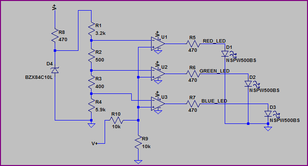
With the quad comparator option (e.g. something like the LM339), a circuit somewhat like this should work (just thrown together, not checked thoroughly, so you will need to refine things if you choose this option - decoupling caps not shown, you will need some on the comparator rails and the zener reference):

The reference is provided by a 10V zener (D4) which is not too exact (you may want to use something more precise, notice the LED turn on values are not exact, but you can adjust the resistor values to compensate) but should do for a rough indicator. Ignore the LED part number and resistor values - they are just what LTSpice had handy (you will have to adjust the resistor values for each LEDs voltage drop to get your required current)
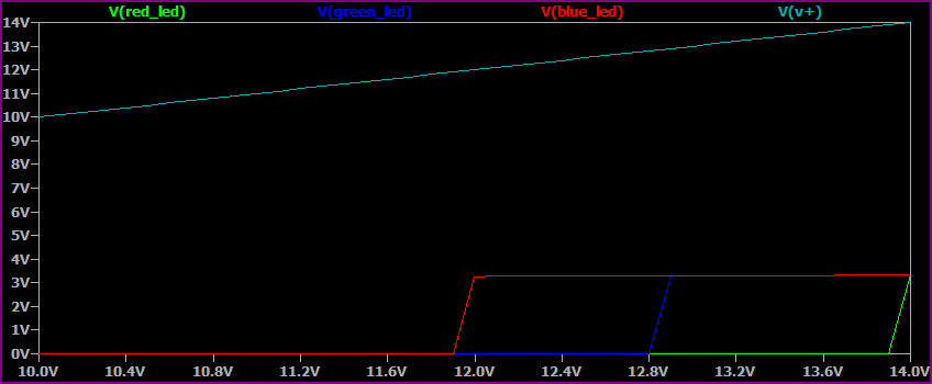
Simulation:

The X axis is the sweep of the supply voltage (V+) from 10V to 14V, you can see each colour LED turning on near it's respective voltage (you will need to tune for precision, as the zener reference also changes slightly with the supply voltage, or use a better reference as mentioned above)
