I'm looking for the circuit to automatically switch the load (< 0.5 A) between the main power source (USB) and back-up (battery) without a specialized IC and without the functionality of charging the battery.
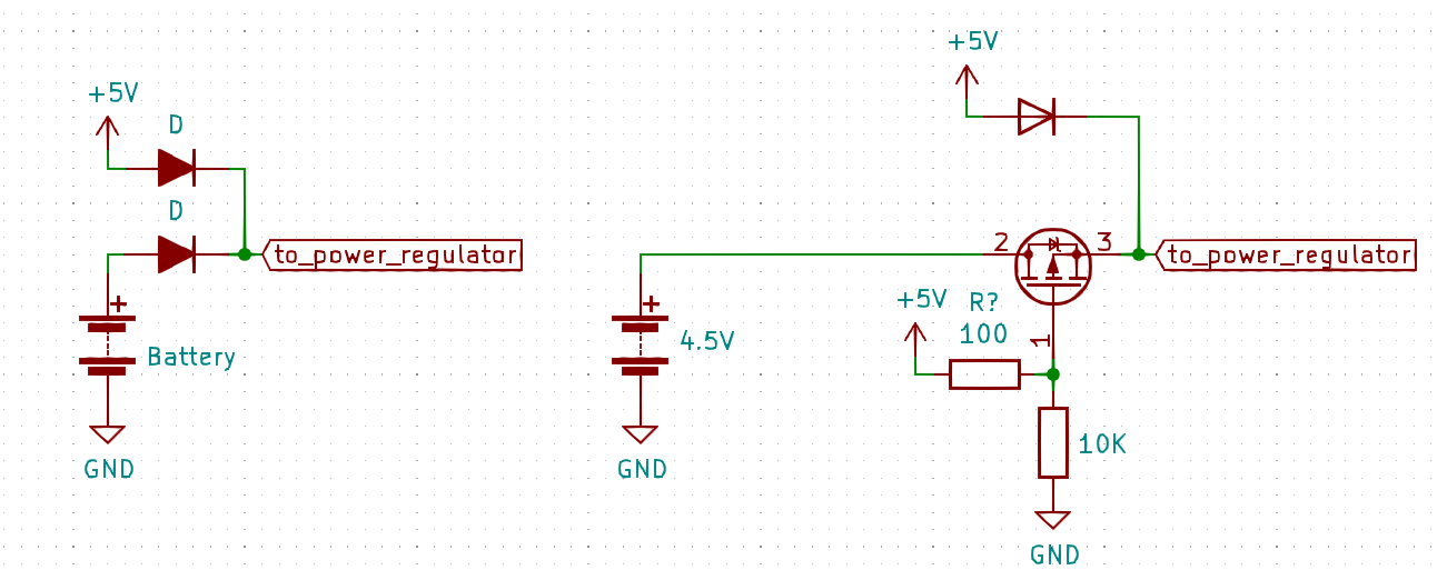
I found two options:
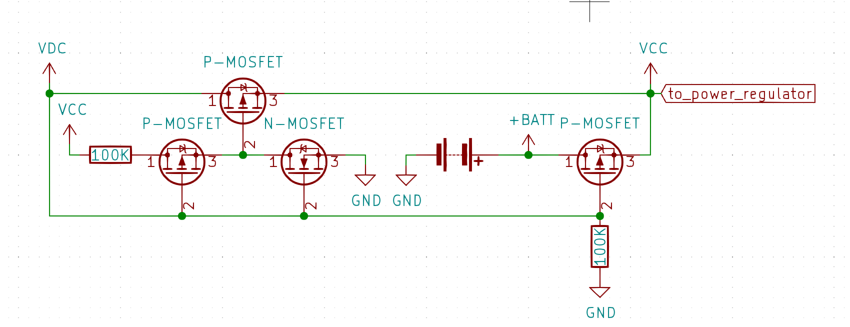
I wonder if a similar solution can be implemented with MOSFETs only and came up with the following circuit:
Where VDC is the external power source, +BATT is voltage from battery, and VCC is the output voltage (automatically switched).
To my understanding (I'm not an EE) this should work as follows:
- if
VDCis connected:- the top P-MOSFET connects the
VDCtoVCCsince the lower N-MOSFET shortens the gate of top P-MOSFET toGNDand opens it - other P-MOSFETs are closed.
VDC=VCC
- the top P-MOSFET connects the
- if
VDCis not connected:- the
VDCis pulled toGND, it opens the left bottom P-MOSFET, which pulls the top P-MOSFET to theVCCand closes it to prevent the back-flow fromVCCtoVDD - P-MOSFET connected to battery is open and connects the battery to load
VCC=+BATT
- the
My questionas are:
- Is it going to work? In case if
VDCis USB and+BATTis 3xAAA batteries? Or if+BATTis a LiIon battery? - Is this solution any better in terms of saving energy than option with 2 diodes and/ one diode and mosfet? Are the voltage drops lower in such schematic?
- Are there any other problems in this schematics except the hustle to find P-mosfers which can be open from small batteries voltage?
- This circuit is going to work only if
VDC> (+BATT+ body voltage drop on right bottom P-MOSFET)?


